ICGOO在线商城 > DS1374U-3+
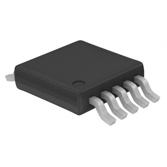
 Datasheet下载
- 型号: DS1374U-3+
- 制造商: Maxim
- 库位|库存: xxxx|xxxx
- 要求:
| 数量阶梯 | 香港交货 | 国内含税 |
| +xxxx | $xxxx | ¥xxxx |
查看当月历史价格
查看今年历史价格
DS1374U-3+产品简介:
ICGOO电子元器件商城为您提供DS1374U-3+由Maxim设计生产,在icgoo商城现货销售,并且可以通过原厂、代理商等渠道进行代购。 提供DS1374U-3+价格参考以及MaximDS1374U-3+封装/规格参数等产品信息。 你可以下载DS1374U-3+参考资料、Datasheet数据手册功能说明书, 资料中有DS1374U-3+详细功能的应用电路图电压和使用方法及教程。
| 参数 | 数值 |
| 产品目录 | 集成电路 (IC)半导体 |
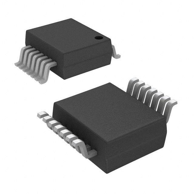
| 描述 | IC RTC BINARY CNT I2C 10-USOP实时时钟 I2C 32-Bit Binary Counter Watchdog |
| 产品分类 | |
| 品牌 | Maxim Integrated |
| 产品手册 | |
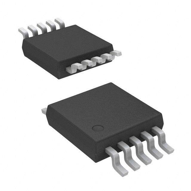
| 产品图片 |
|
| rohs | 符合RoHS无铅 / 符合限制有害物质指令(RoHS)规范要求 |
| 产品系列 | 时钟和计时器IC,实时时钟,Maxim Integrated DS1374U-3+- |
| 数据手册 | |
| 产品型号 | DS1374U-3+ |
| RTC存储容量 | 32 B |
| RTC总线接口 | I2C |
| 产品培训模块 | http://www.digikey.cn/PTM/IndividualPTM.page?site=cn&lang=zhs&ptm=25703http://www.digikey.cn/PTM/IndividualPTM.page?site=cn&lang=zhs&ptm=25705 |
| 产品目录页面 | |
| 产品种类 | |
| 供应商器件封装 | 10-uMAX |
| 其它名称 | DS1374U3 |
| 功能 | Watchdog Timekeeper, Alarm, Binary Counter |
| 包装 | 管件 |
| 商标 | Maxim Integrated |
| 存储容量 | - |
| 安装类型 | 表面贴装 |
| 安装风格 | SMD/SMT |
| 封装 | Tube |
| 封装/外壳 | 10-TFSOP,10-MSOP(0.118",3.00mm 宽) |
| 封装/箱体 | uSOP-10 |
| 工作温度 | -40°C ~ 85°C |
| 工厂包装数量 | 50 |
| 应用说明 | 点击此处下载产品Datasheet点击此处下载产品Datasheet点击此处下载产品Datasheet点击此处下载产品Datasheet点击此处下载产品Datasheet点击此处下载产品Datasheet点击此处下载产品Datasheet点击此处下载产品Datasheet点击此处下载产品Datasheet点击此处下载产品Datasheet点击此处下载产品Datasheet点击此处下载产品Datasheet |
| 接口 | I²C,2 线串口 |
| 日期格式 | 二进制 |
| 时间格式 | 二进制 |
| 最大工作温度 | + 85 C |
| 最小工作温度 | - 40 C |
| 标准包装 | 1 |
| 特性 | 警报器,方波输出,涓流充电器,监视计时器 |
| 电压-电源 | 2.7 V ~ 3.3 V |
| 电压-电源,电池 | 1.3 V ~ 3.7 V |
| 电池备用开关 | Yes |
| 电流-计时(最大) | 125µA @ 2.7V ~ 3.3V |
| 电源电压-最大 | 3.3 V |
| 电源电压-最小 | 2.7 V |
| 类型 | 二进制计数器 |
| 系列 | DS1374U |
| 零件号别名 | 90-1374U+003 DS1374U |



- 商务部:美国ITC正式对集成电路等产品启动337调查
- 曝三星4nm工艺存在良率问题 高通将骁龙8 Gen1或转产台积电
- 太阳诱电将投资9.5亿元在常州建新厂生产MLCC 预计2023年完工
- 英特尔发布欧洲新工厂建设计划 深化IDM 2.0 战略
- 台积电先进制程称霸业界 有大客户加持明年业绩稳了
- 达到5530亿美元!SIA预计今年全球半导体销售额将创下新高
- 英特尔拟将自动驾驶子公司Mobileye上市 估值或超500亿美元
- 三星加码芯片和SET,合并消费电子和移动部门,撤换高东真等 CEO
- 三星电子宣布重大人事变动 还合并消费电子和移动部门
- 海关总署:前11个月进口集成电路产品价值2.52万亿元 增长14.8%
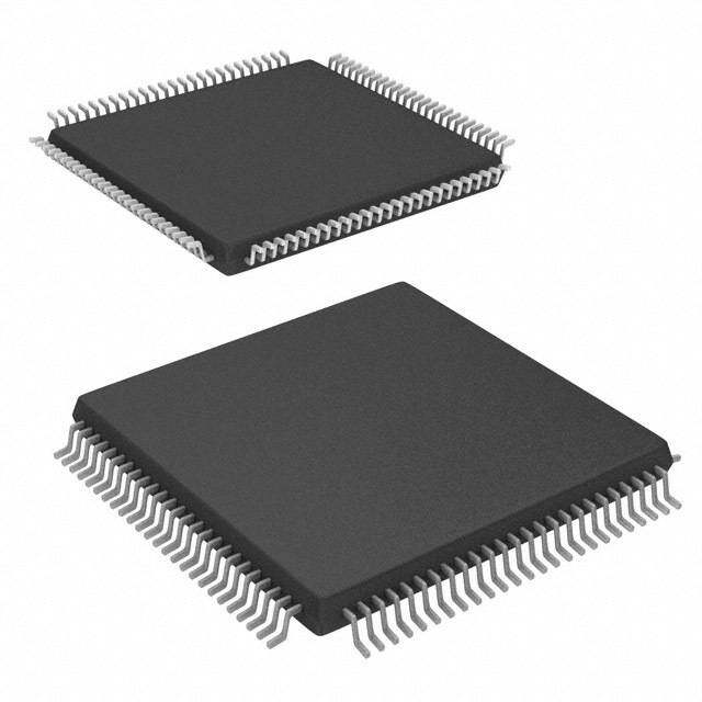
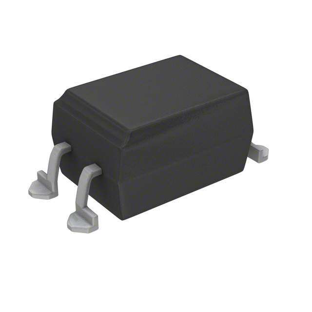


PDF Datasheet 数据手册内容提取
19-5484; Rev 4; 8/10 I2C, 32-Bit Binary Counter Watchdog RTC with Trickle Charger and Reset Input/Output General Description Features D The DS1374 is a 32-bit binary counter designed to contin- ♦ 32-Bit Binary Counter S uously count time in seconds. An additional counter gen- ♦ Second Binary Counter Provides Time-of-Day 1 erates a periodic alarm or serves as a watchdog timer. If Alarm, Watchdog Timer, or NV RAM 3 disabled, this counter can be used as 3 bytes of non- ♦ Separate Square-Wave and Interrupt Output Pins 7 volatile (NV) RAM. Separate output pins are provided for an interrupt and a square wave at one of four selectable ♦ I2C Serial Interface 4 frequencies. A precision temperature-compensated refer- ♦ Automatic Power-Fail Detect and Switch Circuitry ence and comparator circuit monitor the status of VCC to ♦ Single-Pin Pushbutton Reset Input/Open-Drain detect power failures, provide a reset output, and auto- Reset Output matically switch to the backup supply when necessary. ♦ Low-Voltage Operation Additionally, the reset pin is monitored as a pushbutton input for externally generating a reset. The device is pro- ♦ Trickle-Charge Capability grammed serially through an I2C serial interface. ♦ -40°C to +85°C Operating Temperature Range ♦ 10-Pin µSOP, 16-Pin SO ♦ Available in a Surface-Mount Package with an Applications Integrated Crystal (DS1374C) ♦ Underwriters Laboratories (UL) Recognized Portable Instruments Point-of-Sale Equipment Typical Operating Circuit Medical Equipment Telecommunications RPU = tr/CB VCC VCC CRYSTAL RPU RPU VCC X1 X2 VCC SQW SCL CPU SDA DS1374 INT INT PRIMARY VBACKUP BATTERY, RST RST GND RECHARGEABLE N.O. BATTERY, OR PUSHBUTTON SUPER CAPACITOR Pin Configurations appear at the end of the data sheet. RESET Ordering Information PART TEMP RANGE VOLTAGE (V) PIN-PACKAGE TOP MARK** DS1374C-18# -40°C to +85°C 1.8 16 SO (300 mils) DS1374C-18 DS1374C-3# -40°C to +85°C 3.0 16 SO (300 mils) DS1374C-3 DS1374C-33# -40°C to +85°C 3.3 16 SO (300 mils) DS1374C-33 DS1374U-18+ -40°C to +85°C 1.8 10 μSOP DS1374-18 DS1374U-3+ -40°C to +85°C 3.0 10 μSOP DS1374-3 DS1374U-33+ -40°C to +85°C 3.3 10 μSOP DS1374-33 #Denotes a RoHS-compliant device that may include lead that is exempt under RoHS requirements. The lead finish is JESD97 category e3, and is compatible with both lead-based and lead-free soldering processes. +Denotes a lead(Pb)-free/RoHS-compliant package. **A "#" anywhere on the top mark denotes a RoHS-compliant package. A “+” anywhere on the top mark denotes a lead(Pb)-free package. ______________________________________________Maxim Integrated Products 1 For pricing, delivery, and ordering information,please contact Maxim Directat 1-888-629-4642, or visit Maxim’s website at www.maxim-ic.com.
I2C, 32-Bit Binary Counter Watchdog RTC with Trickle Charger and Reset Input/Output 4 ABSOLUTE MAXIMUM RATINGS 7 Voltage Range on VCCPin Relative to Ground.....-0.3V to +6.0V Junction-to-Case Thermal Resistance (θJC) (Note 1) 3 Voltage Range on SDA or SCL 16-Pin SO.....................................................................23°C/W 1 Relative to Ground....................................-0.3V to VCC+ 0.3V 10-Pin µSOP.................................................................39°C/W Junction-to-Ambient Thermal Resistance (θJA) (Note 1) Operating Temperature Range...........................-40°C to +85°C S 16-Pin SO.....................................................................73°C/W Storage Temperature Range.............................-55°C to +125°C D 10-Pin µSOP...............................................................221°C/W Lead Temperature (soldering, 10s).................................+260°C Soldering Temperature (reflow).......................................+260°C Note 1: Package thermal resistances were obtained using the method described in JEDEC specification JESD51-7, using a four- layer board. For detailed information on package thermal considerations, refer to www.maxim-ic.com/thermal-tutorial. Stresses beyond those listed under “Absolute Maximum Ratings” may cause permanent damage to the device. These are stress ratings only, and functional operation of the device at these or any other conditions beyond those indicated in the operational sections of the specifications is not implied. Exposure to absolute maximum rating conditions for extended periods may affect device reliability. RECOMMENDED DC OPERATING CONDITIONS (VCC= VCC(MIN)to VCC(MAX), TA= -40°C to +85°C, unless otherwise noted.) (Note 2) PARAMETER SYMBOL CONDITIONS MIN TYP MAX UNITS DS1374-33 2.97 3.3 5.50 Supply Voltage VCC DS1374-3 2.7 3.0 3.3 V (Notes 3, 4) DS1374-18 1.71 1.8 1.89 Input Logic 1 VIH (Note 3) 0.7 x VCC VCC + 0.3 V +0.3 x Input Logic 0 VIL (Note 3) -0.3 V VCC Pullup Resistor Voltage (INT, VPU (Note 3) 5.5 V SQW, SDA, SCL), VCC = 0V DS1374-33 2.70 2.88 2.97 Power-Fail Voltage VPF DS1374-3 2.45 2.6 2.7 V (Note 3) DS1374-18 1.51 1.6 1.71 VCC Backup Supply Voltage DS1374-33 1.3 3.0 VBACKUP (MAX) V (Notes 3, 4, 5) DS1374-3, DS1374-18 1.3 3.0 3.7 2 _____________________________________________________________________
I2C, 32-Bit Binary Counter Watchdog RTC with Trickle Charger and Reset Input/Output DC ELECTRICAL CHARACTERISTICS D (VCC= VCC(MIN)to VCC(MAX), TA= -40°C to +85°C, unless otherwise noted.) (Note 2) S PARAMETER SYMBOL CONDITIONS MIN TYP MAX UNITS 1 3 R1 (Note 6) 250 Trickle-Charge Current-Limiting 7 R2 (Note 7) 2000 (cid:1) Resistors 4 R3 (Note 8) 4000 Input Leakage ILI (Note 9) -1 +1 I/O Leakage ILO (Note 10) -1 +1 μA RST Pin I/O Leakage ILORST (Note 11) -200 +1 SDA Logic 0 Output (VOL = 0.4V) IOLSDA 3.0 mA VCC > 2V; VOL = 0.4V 3.0 RST, SQW, and INT Logic 0 mA IOL1 1.71V < VCC < 2V; VOL = 0.2 VCC 3.0 Outputs (Note 12) 1.3V < VCC < 1.71V; VOL = 0.2 VCC 250 μA DS1374-18 75 150 Active Supply Current ICCA DS1374-3 110 200 μA (Notes 12, 13) DS1374-33 180 300 DS1374-18 60 100 Standby Current (Notes 12, 14) ICCS DS1374-3 80 125 μA DS1374-33 115 175 VBACKUP Leakage Current IBACKUPLKG 100 nA (VBACKUP = 3.7V) DC ELECTRICAL CHARACTERISTICS (VCC= 0V, VBACKUP= 3.7V, TA= -40°C to +85°C, unless otherwise noted.) (Note 2) PARAMETER SYMBOL CONDITIONS MAX TYP MAX UNITS VBACKUP Current (OSC ON); IBKOSC1 (Note 15) 400 700 nA SQW OFF VBACKUP Current (OSC ON); IBKOSC2 (Notes 15, 16) 600 1000 nA SQW ON (32kHz) VBACKUP Data-Retention Current IBACKUPDR 25 100 nA (OSC OFF) _____________________________________________________________________ 3
I2C, 32-Bit Binary Counter Watchdog RTC with Trickle Charger and Reset Input/Output 4 AC ELECTRICAL CHARACTERISTICS 7 (VCC= VCC(MIN)to VCC(MAX), TA= -40°C to +85°C, unless otherwise noted.) (Note 2) (Figure 1) 3 PARAMETER SYMBOL CONDITIONS MIN TYP MAX UNITS 1 S Fast mode 100 400 SCL Clock Frequency (Note 17) fSCL kHz Standard mode 0 100 D Bus Free Time Between STOP Fast mode 1.3 tBUF μs and START Conditions Standard mode 4.7 Hold Time (Repeated) START Fast mode 0.6 tHD:STA μs Condition (Note 18) Standard mode 4.0 Fast mode 1.3 Low Period of SCL Clock tLOW μs Standard mode 4.7 Fast mode 0.6 High Period of SCL Clock tHIGH μs Standard mode 4.0 Fast mode 0 0.9 Data Hold Time (Notes 19, 20) tHD:DAT μs Standard mode 0 0.9 Fast mode 100 Data Setup Time (Note 21) tSU:DAT ns Standard mode 250 Fast mode 0.6 Start Setup Time tSU:STA μs Standard mode 4.7 Rise Time of Both SDA and SCL Fast mode 20 + 300 tR ns Signals (Note 17) Standard mode 0.1CB 1000 Fall Time of Both SDA and SCL Fast mode 20 + 300 tF ns Signals (Note 17) Standard mode 0.1CB 300 Fast mode 0.6 Setup Time for STOP Condition tSU:STO μs Standard mode 4.7 Capacitive Load for Each Bus Line CB (Note 17) 400 pF I/O Capacitance (SDA, SCL) CI/O (Note 22) 10 pF Pulse Width of Spikes That Must tSP Fast mode 30 ns be Suppressed by the Input Filter Pushbutton Debounce PBDB (Figure 2) 250 ms Reset Active Time tRST (Figure 2) 250 ms Oscillator Stop Flag (OSF) Delay tOSF (Note 23) 100 ms 4 _____________________________________________________________________
I2C, 32-Bit Binary Counter Watchdog RTC with Trickle Charger and Reset Input/Output POWER-UP/POWER-DOWN CHARACTERISTICS D (TA= -40°C to +85°C) (Figure 3) S 1 PARAMETER SYMBOL CONDITIONS MIN TYP MAX UNITS 3 VCC Detect to Recognize Inputs tRPU (Note 24) 250 ms 7 (VCC Rising) 4 VCC Fall Time; VPF(MAX) to tF 300 μs VPF(MIN) VCC Rise Time; VPF(MIN) to tR 0 μs VPF(MAX) WARNING: Under no circumstances are negative undershoots, of any amplitude, allowed when the device is in write protection. Note 2: Limits at -40°C are guaranteed by design and not production tested. Note 3: All voltages are referenced to ground. Note 4: VBACKUPshould not exceed VCCMAXor 3.7V, whichever is greater. Note 5: The use of the 250Ωtrickle-charge resistor is not allowed at VCC> 3.63V and should not be enabled. Note 6: Measured at VCC= typ, VBACKUP= 0V, register 09h = A5h. Note 7: Measured at VCC= typ, VBACKUP= 0V, register 09h = A6h. Note 8: Measured at VCC= typ, VBACKUP= 0V, register 09h = A7h. Note 9: SCL only. Note 10: SDA and SQW and INT. Note 11: The RSTpin has an internal 50kΩpullup resistor to VCC. Note 12: Trickle charger disabled. Note 13: ICCA—SCL clocking at max frequency = 400kHz. Note 14: Specified with I2C bus inactive. Note 15: Measured with a 32.768kHz crystal attached to the X1 and X2 pins. Note 16: WDSTR = 1. BBSQW = 1 is required for operation when VCCis below the power-fail trip point (or absent). Note 17: CB—total capacitance of one bus line in pF. Note 18: After this period, the first clock pulse is generated. Note 19: The maximum tHD:DATonly has to be met if the device does not stretch the low period (tLOW) of the SCL signal. Note 20: A device must internally provide a hold time of at least 300ns for the SDA signal (referred to as the VIHMINof the SCL sig- nal) to bridge the undefined region of the falling edge of SCL. Note 21: A fast-mode device can be used in a standard-mode system, but the requirement tSU:DAT≥to 250ns must be met. This is automatically the case if the device does not stretch the low period of the SCL signal. If such a device does stretch the low period of the SCL signal, it must output the next data bit to the SDA line tRmax + tSU:DAT= 1000 + 250 = 1250ns before the SCL line is released. Note 22: Guaranteed by design. Not production tested. Note 23: The parameter tOSFis the period of time the oscillator must be stopped for the OSF flag to be set over the voltage range of 0V ≤VCC≤VCCMAXand 1.3V ≤VBACKUP≤3.7V. Note 24: This delay applies only if the oscillator is enabled and running. If the EOSCbit is 1, the startup time of the oscillator is added to this delay. _____________________________________________________________________ 5
I2C, 32-Bit Binary Counter Watchdog RTC with Trickle Charger and Reset Input/Output 4 7 3 1 SDA S D tBUF tHD:STA tSP tLOW tR tF SCL tHD:STA tHIGH tSU:STA STOP START tSU:DAT REPEATED tSU:STO START tHD:DAT Figure 1. Data Transfer on I2C Serial Bus RST PBDB tRST Figure 2. Pushbutton Reset Timing VCC VPF(MAX) VPF VPF VPF(MIN) tF tR tRPU tRST RST INPUTS RECOGNIZED DON'T CARE RECOGNIZED HIGH-Z OUTPUTS VALID VALID Figure 3. Power-Up/Power-Down Timing 6 _____________________________________________________________________
I2C, 32-Bit Binary Counter Watchdog RTC with Trickle Charger and Reset Input/Output Typical Operating Characteristics D (VCC= +3.3V, TA= +25°C, unless otherwise noted.) S 1 3 IBAT0SC1 vs. VBAT IBAT0SC2 vs. VBAT IBATOSC1 vs. TEMPERATURE SQUARE-WAVE OFF SQUARE-WAVE ON VBAT = 3.0V 7 550500 VCC = 0V DS1374 toc01 785000 VCC = 0V DS1374 toc02 475 VCC = 0V DS1374 toc03 4 NT (nA) 450 NT (nA) 675000 NT (nA) 450 URRE URRE 600 URRE 425 C C C UPPLY 400 UPPLY 550500 UPPLY S S S 400 350 450 400 300 350 375 1.3 1.8 2.3 2.8 3.3 3.8 4.3 4.8 5.3 1.3 1.8 2.3 2.8 3.3 3.8 4.3 4.8 5.3 -40 -20 0 20 40 60 80 VBAT (V) VBAT (V) TEMPERATURE (°C) ICCA vs. VCC (SQUARE-WAVE ON) OSCILLATOR FREQUENCY vs. VBACKUP 225705 DS1374 toc04 3322776688..78 VCC = 0V DS1374 toc05 225 32768.6 A) μRENT ( 127050 CY (Hz) 32768.5 UR EN 32768.4 UPPLY C 112550 FREQU 32768.3 S 32768.2 100 75 32768.1 50 32768.0 1.8 2.3 2.8 3.3 3.8 4.3 4.8 5.3 1.3 1.8 2.3 2.8 3.3 3.8 4.3 4.8 5.3 VCC (V) VBACKUP (V) VCC FALLING vs. RST DELAY 1000 VCC = 3.0V TO 0V DS1374 toc06 100 μs) Y ( A L DE 10 T E S E R 1 0.1 0.01 0.10 1 10 100 VCC FALLING (V/ms) _____________________________________________________________________ 7
I2C, 32-Bit Binary Counter Watchdog RTC with Trickle Charger and Reset Input/Output 4 Pin Description 7 3 PIN NAME FUNCTION 1 μSOP SO S Connections for a Standard 32.768kHz Quartz Crystal. The internal oscillator circuitry is designed D 1, 2 — X1, X2 for operation with a crystal having a specified load capacitance (CL) of 6pF. Pin X1 is the input to the oscillator and can optionally be connected to an external 32.768kHz oscillator. The output of the internal oscillator, pin X2, is left unconnected if an external oscillator is connected to pin X1. Connection for a Secondary Power Supply. This supply is used to operate the oscillator and counters when VCC is absent. Supply voltage must be held between 1.3V and 3.7V (-18 and -3) or 1.3V and 5.5V (-33) for proper operation. This pin can be connected to a primary cell such as a 3 13 VBACKUP lithium cell. Additionally, this pin can be connected to a rechargeable cell or a super cap when used with the trickle-charge feature. UL recognized to ensure against reverse charging when used with a lithium battery. This pin must be grounded if not used. Active-Low, Open-Drain Output with a Debounced Pushbutton Input. This pin can be activated by a pushbutton reset request, a watchdog alarm condition, or a power-fail event. It has an internal 50k(cid:1) 4 14 RST pullup resistor. No external resistors should be connected. If the crystal oscillator is disabled, the startup time of the oscillator is added to the tRST delay. 5 15 GND Ground Serial Data Input/Output. SDA is the input/output for the 2-wire serial interface. The SDA pin is open 6 16 SDA drain and requires an external pullup resistor. Serial Clock Input. SCL is the clock input for the 2-wire serial interface and is used to synchronize 7 1 SCL data movement on the serial interface. Interupt. This pin is used to output the alarm interrupt or the watchdog reset signal. It is active-low 8 2 INT open drain and requires an external pullup resistor. Square-Wave Output. This pin is used to output the programmable square-wave signal. It is open 9 3 SQW drain and requires an external pullup resistor. 10 4 VCC DC Power for Primary Power Supply — 5–12 N.C. No Connection. Must be connected to ground. X1 1Hz 4.096kHz CLOCK SQW 8.192kHz MUX X2 DIVIDER 32.768kHz 1Hz/4.096kHz INT INT 32-BIT CONTROL POWER COUNTER VCC CONTROL VBACKUP AND ALARM/ 24-BIT GND TRICKLE WATCHDOG COUNTER CHARGE STAT/CTRL/ TRICKLE SDA 2-WIRE SCL INTERFACE RST RST CONTROL DS1374 Figure 4. Functional Diagram 8 _____________________________________________________________________
I2C, 32-Bit Binary Counter Watchdog RTC with Trickle Charger and Reset Input/Output Table 1. Crystal Specifications* D LOCAL GROUND PLANE (LAYER 2) S PARAMETER SYMBOL MIN TYP MAX UNITS 1 Nominal fO 32.768 kHz X1 3 Frequency CRYSTAL 7 Series ESR 45 kΩ X2 4 Resistance Load CL 6 pF Capacitance *The crystal, traces, and crystal input pins should be isolated from RF generating signals. Refer toApplication Note 58: GND Crystal Considerations for Dallas Real-Time Clocks for addi- tional specifications. NOTE: AVOID ROUTING SIGNALS IN THE CROSSHATCHED AREA (UPPER LEFT-HAND QUADRANT) OF THE PACKAGE UNLESS THERE IS A GROUND PLANE BETWEEN THE SIGNAL LINE AND THE PACKAGE. Figure 6. Layout Example COUNTDOWN CHAIN Oscillator Circuit The DS1374 uses an external 32.768kHz crystal. The DS1374 oscillator circuit does not require any external resistors or capacitors to operate. Table 1 specifies several crys- CL1 CL2 RTC REGISTERS tal parameters for the external crystal. Figure 5 shows a functional schematic of the oscillator circuit. The startup time is usually less than 1 second when using a crystal X1 X2 with the specified characteristics. Clock Accuracy CRYSTAL Clock accuracy is dependent upon the accuracy of the Figure 5. Oscillator Circuit Showing Internal Bias Network crystal and the accuracy of the match between the capacitive load of the oscillator circuit and the capacitive Detailed Description load for which the crystal was trimmed. Additional error The DS1374 is a real-time clock with an I2C serial inter- is added by crystal frequency drift caused by tempera- ture shifts. External circuit noise coupled into the oscilla- face. It provides elapsed seconds from a user-defined tor circuit can result in the clock running fast. Figure 6 starting point in a 32-bit counter (Figure 4). A 24-bit shows a typical PC board layout for isolating the crystal counter can be configured as either a watchdog and oscillator from noise. Refer to Application Note 58: counter or an alarm counter. An on-chip oscillator cir- Crystal Considerations with Dallas Real-Time Clocksfor cuit uses a customer-supplied 32.768kHz crystal to detailed information. keep time. A power-control circuit switches operation from VCC to VBACKUP and back when power on VCC is DS1374C Only cycled. The oscillator and counters continue to operate The DS1374C integrates a standard 32,768Hz crystal when powered by either supply. If a rechargeable into the package. Typical accuracy at nominal VCC and backup supply is used, a trickle charger can be 25°C is approximately 10ppm. See Application Note 58 enabled to charge the backup supply while VCCis on. for information about crystal accuracy vs. temperature. _____________________________________________________________________ 9
I2C, 32-Bit Binary Counter Watchdog RTC with Trickle Charger and Reset Input/Output 4 Power Control Address Map 7 The power-control function is provided by a precise, Table 3 shows the address map for the DS1374 regis- 3 temperature-compensated voltage reference and a ters. During a multibyte access, the address pointer 1 comparator circuit that monitors the VCC level. The wraps around to location 00h when it reaches the end of S device is fully accessible and data can be written and the register space (08h). On an I2C START, STOP, or D read when VCC is greater than VPF. However, when address pointer incrementing to location 00h, the current VCC falls below VPF, the internal clock registers are time is transferred to a second set of registers. These blocked from any access. If VPF is less than VBACKUP, secondary registers read the time information, while the the device power is switched from VCC to VBACKUP clock continues to run. This eliminates the need to reread when VCC drops below VPF. If VPF is greater than the registers in case of an update of the main registers VBACKUP, the device power is switched from VCC to during a read. VBACKUP when VCC drops below VBACKUP. The regis- Time-of-Day Counter ters are maintained from the VBACKUP source until VCC is returned to nominal levels (Table 1). After VCC The time-of-day counter is a 32-bit up counter that returns above VPF, read and write access is allowed increments once per second when the oscillator is run- after RSTgoes high (Figure 1). ning. The contents can be read or written by accessing the address range 00h–03h. When the counter is read, Table 2. Power Control the current time of day is latched into a register, which is output on the serial data line while the counter contin- READ/WRITE POWERED ues to increment. SUPPLY CONDITION ACCESS BY Note: Writing to any TOD register will reset the 1Hz VCC < VPF, VCC < VBACKPUP No VBACKUP square wave output. VCC < VPF, VCC > VBACKUP No VCC VCC > VPF, VCC < VBACKUP Yes VCC VCC > VPF, VCC > VBACKUP Yes VCC Table 3. Address Map ADDRESS BIT 7 BIT 6 BIT 5 BIT 4 BIT 3 BIT 2 BIT 1 BIT 0 FUNCTION 00H TOD Counter Byte 0 Time-of-Day Counter 01H TOD Counter Byte 1 Time-of-Day Counter 02H TOD Counter Byte 2 Time-of-Day Counter 03H TOD Counter Byte 3 Time-of-Day Counter 04H WD/ALM Counter Byte 0 Watchdog/Alarm Counter 05H WD/ALM Counter Byte 1 Watchdog/Alarm Counter 06H WD/ALM Counter Byte 2 Watchdog/Alarm Counter 07H EOSC WACE WD/ALM BBSQW WDSTR RS2 RS1 AIE Control 08H OSF 0 0 0 0 0 0 AF Status 09H TCS3 TCS2 TCS1 TCS0 DS1 DS0 ROUT1 ROUT0 Trickle Charger Note:Unless otherwise specified, the state of the registers is not defined when power is first applied. 10 ____________________________________________________________________
I2C, 32-Bit Binary Counter Watchdog RTC with Trickle Charger and Reset Input/Output Watchdog/Alarm Counter If WDSTR = 1 and the counter reaches zero, the AF bit D is set and the counter stops. If AIE = 0, AF remains set The contents of the watchdog/alarm counter, which is a S until cleared by writing it to 0. If AIE = 1, the INT pin separate 24-bit down counter, are accessed in the pulses low for 250ms. At the end of the 250ms pulse, 1 address range 04h–06h. When this counter is written, the the AF bit is cleared and INTbecomes high impedance. 3 counter and a seed register are loaded with the desired value. When the counter is to be reloaded, it uses the The 250ms pulse on INTor RSTcannot be truncated by 7 value in the seed register. When the counter is read, the writing either AF or AIE to zero during the low time. If the 4 current counter value is latched into a register, which is INT counter is written during the 250ms pulse, the output on the serial data line while the counter continues counter starts decrementing upon the pulse completion. to decrement. The watchdog and alarm function operates from VCC or IIf the counter is not needed, it can be disabled and VBAT. When the AF bit is set, INTis pulled low when the used as a 24-bit cache of NV RAM by setting the device is powered by VCCor VBAT. WACE bit in the control register to logic 0. If all 24 bits Note: WACE must be toggled from logic 0 to logic 1 of the watchdog/alarm counter are written to zero, the after the watchdog counter is written from a zero to a counter is disabled, independent of the WACE bit set- nonzero value. ting. When the watchdog counter is is written to a Power-Up/Power-Down Reset and nonzero value, and WACE is written to logic 1, the func- Pushbutton Reset Functions tion of the counter is determined by the WD/ALMbit. When the WD/ALM bit in the control register is set to A precision temperature-compensated reference and logic 0, the WD/ALMcounter decrements every second comparator circuit monitors the status of VCC. When an until it reaches zero. At this point, the AF bit in the sta- out-of-tolerance condition occurs, an internal power-fail tus register is set to 1 and the counter is reloaded and signal is generated that forces the RST pin low and restarted. AF remains set until cleared by writing it to 0. blocks read/write access to the DS1374. When VCC If AIE = 1, the INT pin goes active whenever AF = 1. returns to an in-tolerance condition, the RST pin is held WDSTR does not affect operation when WD/ALM= 0. low for 250ms to allow the power supply to stabilize. If the EOSCbit is set to a logic 1 (to disable the oscillator in When the WD/ALM bit is set to logic 1, the WD/ALM battery-backup mode), the reset signal is kept active for counter decrements every 1/4096 of a second (approx- 250ms plus the startup time of the oscillator. imately every 244us) until it reaches zero. When any of the watchdog counters bytes are read, the seed value The DS1374 provides for a pushbutton switch to be con- is reloaded and the counter restarts. Writing to the nected to the RSToutput pin. When the DS1374 is not in watchdog counter updates the seed value and reloads a reset cycle, it continuously monitors the RST signal for the counter with the new seed value. When the counter a low-going edge. If an edge is detected, the DS1374 reaches zero, the AF bit is set and the counter stops. debounces the switch by pulling the RST pin low and inhibits read/write access. After the internal 250ms timer If WDSTR = 0, the RST pin pulses low for 250ms, and has expired, the device continues to monitor the RST accesses to the device are inhibited. At the end of the line. If the line is still low, the DS1374 continues to moni- 250ms pulse, the AF bit is cleared to zero, the RST pin tor the line, looking for a rising edge. Upon detecting becomes high impedance, and read/write access to release, the DS1374 forces the RST pin low and holds it the device is enabled. low for an additional 250ms. ____________________________________________________________________ 11
I2C, 32-Bit Binary Counter Watchdog RTC with Trickle Charger and Reset Input/Output 4 Bit 7 Bit 6 Bit 5 Bit 4 Bit 3 Bit 2 Bit 1 Bit 0 7 EOSC WACE WD/ALM BBSQW WDSTR RS2 RS1 AIE 3 1 Special Purpose Registers logic 0, the SQW pin goes high impedance when VCC S falls below the power-fail trip point. This bit is disabled The DS1374 has two additional registers (07h–08h) that D control the WD/ALMcounter and the square-wave, inter- (logic 0) when power is first applied. rupt, and reset outputs. Bit 3/Watchdog Reset Steering Bit (WDSTR). This bit selects which output pin the watchdog-reset signal Control Register (07h) occurs on. When the WDSTR bit is set to logic 0, a Bit 7/Enable Oscillator (EOSC). When set to logic 0, 250ms pulse occurs on the RSTpin if WD/ALM= 1 and the oscillator is started. When set to logic 1, the oscilla- the WD/ALM counter reaches zero. The 250ms reset tor is stopped. When this bit is set to logic 1, the oscilla- pulse occurs on the INT pin when the WDSTR bit is set tor is stopped and the DS1374 is placed into a to logic 1. This bit is logic 0 when power is first applied. low-power standby mode (IDDR). This bit is clear (logic Bits 2, 1/Rate Select (RS2 and RS1). These bits con- 0) when power is first applied. When the DS1374 is trol the frequency of the square-wave output when the powered by VCC, the oscillator is always on regardless square wave has been enabled. Table 4 shows the of the state of the EOSCbit. square-wave frequencies that can be selected with the Bit 6/WD/AALLMM Counter Enable (WACE). When set to RS bits. These bits are both set (logic 1) when power is logic 1, the WD/ALM counter is enabled. When set to first applied. logic 0, the WD/ALM counter is disabled, and the 24 Bit 0/Alarm Interrupt Enable (AIE). When set to logic bits can be used as NV RAM. This bit is clear (logic 0) 1, this bit permits the alarm flag (AF) bit in the status when power is first applied. register to assert INT (when WDSTR = 1). When set to Bit 5/WD/AALLMM Counter Select (WD/ALM). When set to logic 0 or WDSTR is set to logic 0, the AF bit does not logic 0, the counter decrements every second until it initiate the INTsignal. If the WD/ALMbit is set to logic 1 reaches zero and is then reloaded and restarted. When and the AF flag is set, writing AIE to zero does not trun- set to logic 1, the WD/ALM counter decrements every cate the 250ms pulse on the INT pin. The AIE bit is at 1/4096 of a second (approximately every 244µs) until it logic 0 when power is first applied. The INToutput is reaches zero, sets the AF bit in the status register, and available while the device is powered by either supply. stops. If any of the WD/ALM counter registers are accessed before the counter reaches zero, the counter Table 4. Square-Wave Output Frequency is reloaded and restarted. This bit is clear (logic 0) RS2 RS1 SQUARE-WAVE OUTPUT FREQUENCY when power is first applied. 0 0 1Hz Bit 4/Battery-Backed Square-Wave Enable (BBSQW). This bit, when set to logic 1, enables the square-wave 0 1 4.096kHz output when VCC is absent and when the DS1374 is 1 0 8.192kHz being powered by the VBACKUP pin. When BBSQW is 1 1 32.768kHz 12 ____________________________________________________________________
I2C, 32-Bit Binary Counter Watchdog RTC with Trickle Charger and Reset Input/Output Bit 7 Bit 6 Bit 5 Bit 4 Bit 3 Bit 2 Bit 1 Bit 0 D OSF 0 0 0 0 0 0 AF S 1 Status Register (08h) select (TCS) bits (bits 4–7) control the selection of the 3 Bit 7/Oscillator Stop Flag (OSF). A logic 1 in this bit trickle charger. To prevent accidental enabling, only a 7 indicates that the oscillator either is stopped or was pattern of 1010 enables the trickle charger. All other 4 stopped for some period of time and can be used to patterns disable the trickle charger. The trickle charger judge the validity of the timekeeping data. This bit is set is disabled when power is first applied. The diode to logic 1 any time the oscillator stops. The following select (DS) bits (bits 2, 3) select whether or not a diode are examples of conditions that can cause the OSF bit is connected between VCC and VBACKUP. If DS is 01, to be set: no diode is selected; if DS is 10, a diode is selected. The ROUT bits (bits 0, 1) select the value of the resistor 1) The first time power is applied. connected between VCC and VBACKUP. Table 5 shows 2) The voltage present on both VCC and VBACKUP are the resistor selected by the resistor select (ROUT) bits insufficient to support oscillation. and the diode selected by the diode select (DS) bits. 3) The EOSCbit is turned off. Warning:The ROUT value of 250Ωmust not be select- 4) External influences on the crystal (i.e., noise, leak- ed whenever VCCis greater than 3.63V. age, etc.). The user determines diode and resistor selection This bit remains at logic 1 until written to logic 0. according to the maximum current desired for battery or super cap charging. The maximum charging current can Bit 0/Alarm Flag (AF). A logic 1 in the alarm flag bit be calculated as illustrated in the following example. indicates that the WD/ALM counter reached zero. If WD/ALM is set to zero and the AIE bit = 1, the INT pin Assume that a system power supply of 3.3V is applied goes low and stays low until AF is cleared. AF is to VCCand a super cap is connected to VBACKUP. Also cleared when written to logic 0. This bit can only be assume the trickle charger has been enabled with a written to logic 0. Attempting to write logic 1 leaves the diode and resistor R2 between VCC and VBACKUP. The value unchanged. If WD/ALM is set to 1 and the AIE maximum current IMAX would therefore be calculated bit = 1, the INT pin pulses low for 250ms when the as follows: WD/ALM counter reaches zero and sets AF = 1. At the IMAX= (3.3V - diode drop) / R2 ≈(3.3V - 0.7V) / 2kΩ≈ pulse completion, the DS1374 clears the AF bit to zero. 1.3mA If the 250ms pulse is active, writing AF to zero does not As the super cap changes, the voltage drop between truncate the pulse. VCCand VBACKUPdecreases and therefore the charge Trickle-Charge Register (10h) current decreases. The simplified schematic in Figure 7 shows the basic components of the trickle charger. The trickle-charge Table 5. Trickle Charge Register TCS3 TCS2 TCS1 TCS0 DS1 DS0 ROUT1 ROUT0 FUNCTION X X X X 0 0 X X Disabled X X X X 1 1 X X Disabled X X X X X X 0 0 Disabled 1 0 1 0 0 1 0 1 No diode, 250Ω resistor 1 0 1 0 1 0 0 1 One diode, 250Ω resistor 1 0 1 0 0 1 1 0 No diode, 2kΩ resistor 1 0 1 0 1 0 1 0 One diode, 2kΩ resistor 1 0 1 0 0 1 1 1 No diode, 4kΩ resistor 1 0 1 0 1 0 1 1 One diode, 4kΩ resistor 0 0 0 0 0 0 0 0 Power-on reset value ____________________________________________________________________ 13
I2C, 32-Bit Binary Counter Watchdog RTC with Trickle Charger and Reset Input/Output 4 7 BIT 7 BIT 6 BIT 5 BIT 4 BIT 3 BIT 2 BIT 1 BIT 0 TCS3 TCS2 TCS1 TCS0 DS1 DS0 ROUT1 ROUT0 3 1 TCS0-3 = TRICKLE CHARGER SELECT DS0-1 = DIODE SELECT S 1 OF 16 SELECT TOUT0-1 = RESISTOR SELECT 1 OF 2 1 OF 3 NOTE: ONLY 1010b D SELECT SELECT ENABLES CHARGER R1 250Ω R2 VCC 2kΩ VBACKUP R3 4kΩ Figure 7. Programmable Trickle Charger SDA MSB SLAVE ADDRESS R/W ACKNOWLEDGEMENT DIRECTION SIGNAL FROM RECEIVER BIT ACKNOWLEDGEMENT SIGNAL FROM RECEIVER SCL 1 2 6 7 8 9 1 2 3–7 8 9 ACK ACK START STOP CONDITION CONDITION REPEATED IF MORE BYTES OR REPEATED ARE TRANSFERED START CONDITION Figure 8. I2C Data Transfer Overview I2C Serial Data Bus and SCL. A standard mode (100kHz max clock rate) and a fast mode (400kHz max clock rate) are defined The DS1374 supports the I2C bus protocol. A device within the bus specifications. The DS1374 works in both that sends data onto the bus is defined as a transmitter modes. and a device receiving data is a receiver. The device that controls the message is called a master. The The following bus protocol has been defined (Figure 8): devices that are controlled by the master are slaves. A • Data transfer can be initiated only when the bus is master device that generates the serial clock (SCL), not busy. controls the bus access, and generates the START and • During data transfer, the data line must remain sta- STOP conditions must control the bus. The DS1374 ble whenever the clock line is high. Changes in the operates as a slave on the I2C bus. Connections to the data line while the clock line is high can be interpret- bus are made through the open-drain I/O lines SDA ed as control signals. 14 ____________________________________________________________________
I2C, 32-Bit Binary Counter Watchdog RTC with Trickle Charger and Reset Input/Output D ASDLDARVEES S R/W ADRDEGRIESSTSE R(n) DATA (n) DATA (n + 1) DATA (n + x) ASDLDARVEES S R/W DATA (n) DATA (n + 1) DATA (n + 2) DATA (n + x) S S 1101000 0 A XXXXXXXX A XXXXXXXX A XXXXXXXX A XXXXXXXX P S 1101000 1 A XXXXXXXX A XXXXXXXX A XXXXXXXX A XXXXXXXX /A 1 SAP --- SASTCTAOKRPNTOWLEDGE (X+D1A BTyAt eTsR +A NASckFnEoRwRlEeDdge) SAP --- SASTCTAOKRPNTOWLEDGE (X+D1A BTyAt eTsR +A NASckFnEoRwRlEeDdge) 37 RD/IWRE -C RTIEOAND /BWITRITE OR /RA/ W- N- ORTE AADC/KWNROITWEL OEDRGE 4 DIRECTION BIT Figure 9. I2C Write Protocol Figure 10. I2C Read Protocol Accordingly, the following bus conditions have been the slave must leave the data line high to enable defined: the master to generate the STOP condition. Bus not busy: Both data and clock lines remain Figures 9 and 10 detail how data transfer is accom- high. plished on the 2-wire bus. Depending on the state of the R/Wbit, two types of data transfer are possible: Start data transfer: A change in the state of the data line from high to low, while the clock line is Data transfer from a master transmitter to a high, defines a START condition. slave receiver. The first byte transmitted by the master is the slave address. Next follows a number Stop data transfer: A change in the state of the of data bytes. The slave returns an acknowledge data line from low to high, while the clock line is bit after each received byte. high, defines a STOP condition. Data transfer from a slave transmitter to a mas- Data valid: The state of the data line represents ter receiver. The master transmits the first byte valid data when, after a START condition, the data (the slave address). The slave then returns an line is stable for the duration of the high period of acknowledge bit. Next follows a number of data the clock signal. The data on the line must be bytes transmitted by the slave to the master. The changed during the low period of the clock signal. master returns an acknowledge bit after all There is one clock pulse per bit of data. received bytes other than the last byte. At the end Each data transfer is initiated with a START condi- of the last received byte, a “not acknowledge” is tion and terminated with a STOP condition. The returned. number of data bytes transferred between the The master device generates the serial clock puls- START and the STOP conditions is not limited, and es and the START and STOP conditions. A transfer is determined by the master device. The informa- is ended with a STOP condition or with a repeated tion is transferred byte-wise and each receiver START condition. Since a repeated START condi- acknowledges with a ninth bit. A standard mode tion is also the beginning of the next serial transfer, (100kHz clock rate) and a fast mode (400kHz clock rate) are defined within the I2C bus specifications. the bus is not released. The DS1374 can operate in the following two modes: Acknowledge: Each receiving device, when addressed, is obliged to generate an acknowledge Slave Receiver Mode (Write Mode): Serial data after the reception of each byte. The master device and clock data are received through SDA and SCL. must generate an extra clock pulse that is associat- After each byte is received, an acknowledge bit is ed with this acknowledge bit. transmitted. START and STOP conditions are rec- ognized as the beginning and end of a serial trans- A device that acknowledges must pull down the fer. Address recognition is performed by hardware SDA line during the acknowledge clock pulse in after reception of the slave address and direction such a way that the SDA line is stable low during bit. The slave address byte is the first byte the high period of the acknowledge-related clock received after the master generates a START con- pulse. Setup and hold times must be considered. A dition. The slave address byte contains the 7-bit master must signal an end of data to the slave by DS1374 address, which is 1101000, followed by not generating an acknowledge bit on the last byte the direction bit (R/W), which is zero for a write. that has been clocked out of the slave. In this case, After receiving and decoding the slave address byte, the DS1374 outputs an acknowledge on SDA. ____________________________________________________________________ 15
I2C, 32-Bit Binary Counter Watchdog RTC with Trickle Charger and Reset Input/Output 4 After the DS1374 acknowledges the slave address Handling, PC Board Layout, and 7 + write bit, the master transmits a register address Assembly to the DS1374. This sets the register pointer on the 3 DS1374, with the DS1374 acknowledging the trans- The DS1374C package contains a quartz tuning-fork 1 fer. The master can then transmit zero or more crystal. Pick-and-place equipment can be used, but S bytes of data, with the DS1374 acknowledging precautions should be taken to ensure that excessive D each byte received. The register pointer increments shocks are avoided. Ultrasonic cleaning should be after each data byte is transferred. The master gen- avoided to prevent damage to the crystal. erates a STOP condition to terminate the data write. Avoid running signal traces under the package, unless Slave Transmitter Mode (Read Mode): The first a ground plane is placed between the package and the byte is received and handled as in the slave receiv- signal line. All no connect (N.C.) pins must be connect- er mode. However, in this mode, the direction bit ed to ground. indicates that the transfer direction is reversed. Moisture-sensitive packages are shipped from the facto- Serial data is transmitted on SDA by the DS1374, ry dry-packed. Handling instructions listed on the pack- while the serial clock is input on SCL. START and age label must be followed to prevent damage during STOP conditions are recognized as the beginning reflow. Refer to the IPC/JEDEC J-STD-020 standard for and end of a serial transfer. Address recognition is moisture-sensitive device (MSD) classifications. performed by hardware after reception of the slave address and direction bit. The slave address byte is the first byte received after the START condition is generated by the master. The slave address byte contains the 7-bit DS1374 address, which is 1101000, followed by the direction bit (R/W), which is 1 for a read. After receiving and decoding the slave address byte, the DS1374 outputs an acknowledge on SDA. The DS1374 then begins to transmit data starting with the register address pointed to by the register pointer. If the register pointer is not written to before the initiation of a read mode, the first address that is read is the last one stored in the register pointer. The DS1374 must receive a not acknowledge to end a read. 16 ____________________________________________________________________
I2C, 32-Bit Binary Counter Watchdog RTC with Trickle Charger and Reset Input/Output Pin Configurations D S 1 TOP VIEW 3 7 SCL 1 16 SDA 4 X1 1 10 VCC INT 2 15 GND X2 2 9 SQW DS1374 SQW 3 14 RST VBACKUP 3 8 INT RST 4 7 SCL VCC 4 DS1374C 13 VBACKUP GND 5 6 SDA N.C. 5 12 N.C. N.C. 6 11 N.C. μSOP N.C. 7 10 N.C. N.C. 8 9 N.C. SO (0.300") Chip Information Package Information PROCESS: CMOS For the latest package outline information and land patterns, go to www.maxim-ic.com/packages. Note that a “+”, “#”, or SUBSTRATE CONNECTED TO GROUND “-” in the package code indicates RoHS status only. Package drawings may show a different suffix character, but the drawing pertains to the package regardless of RoHS status. PACKAGE PACKAGE OUTLINE LAND TYPE CODE NO. PATTERN NO. 16 SO (0.300”) W16#H2 21-0042 90-0107 10 µSOP (3.0mm) U10+2 21-0061 90-0330 ____________________________________________________________________ 17
I2C, 32-Bit Binary Counter Watchdog RTC with Trickle Charger and Reset Input/Output 4 Revision History 7 3 REVISION REVISION DESCRIPTION PAGES NUMBER DATE CHANGED 1 S Removed leaded parts from the Ordering Information table; in the AbsoluteMaximum Ratings section, added the thermal information, lead information, and new Note 1, and D updated the soldering information; in the Control Register (07h) section, corrected the 1–5, 12, 16, 3 8/10 references of INTCN to WDSTR in the AIE bit description; removed the section about 17 the SO package reflow in the Handling, PC Board Layout, and Assembly section; added the land pattern no. to the Package Information table Maxim cannot assume responsibility for use of any circuitry other than circuitry entirely embodied in a Maxim product. No circuit patent licenses are implied. Maxim reserves the right to change the circuitry and specifications without notice at any time. 18 ____________________Maxim Integrated Products, 120 San Gabriel Drive, Sunnyvale, CA 94086 408-737-7600 © 2010 Maxim Integrated Products Maxim is a registered trademark of Maxim Integrated Products, Inc. is a registered trademark of Maxim Integrated Products, Inc.
Mouser Electronics Authorized Distributor Click to View Pricing, Inventory, Delivery & Lifecycle Information: M axim Integrated: DS1374C-18# DS1374C-3# DS1374C-3#T&R DS1374C-33# DS1374C-33#T&R DS1374U-18+ DS1374U-3+T&R DS1374U-33+T&R DS1374U-3+ DS1374U-33 DS1374U-33+