ICGOO在线商城 > MAX1230BCTI+

 Datasheet下载
- 型号: MAX1230BCTI+
- 制造商: Maxim
- 库位|库存: xxxx|xxxx
- 要求:
| 数量阶梯 | 香港交货 | 国内含税 |
| +xxxx | $xxxx | ¥xxxx |
查看当月历史价格
查看今年历史价格
MAX1230BCTI+产品简介:
ICGOO电子元器件商城为您提供MAX1230BCTI+由Maxim设计生产,在icgoo商城现货销售,并且可以通过原厂、代理商等渠道进行代购。 提供MAX1230BCTI+价格参考以及MaximMAX1230BCTI+封装/规格参数等产品信息。 你可以下载MAX1230BCTI+参考资料、Datasheet数据手册功能说明书, 资料中有MAX1230BCTI+详细功能的应用电路图电压和使用方法及教程。
| 参数 | 数值 |
| 产品目录 | 集成电路 (IC)半导体 |
| 描述 | IC ADC 12-BIT 300KSPS 28-TQFN模数转换器 - ADC 12-Bit 16Ch 300ksps 5.25V Precision ADC |
| 产品分类 | |
| 品牌 | Maxim Integrated |
| 产品手册 | |
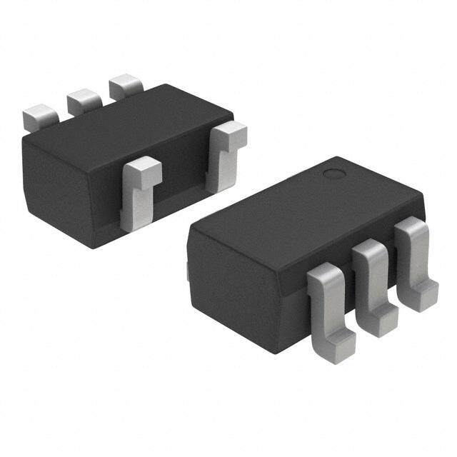
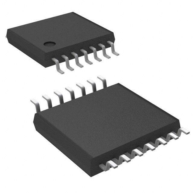
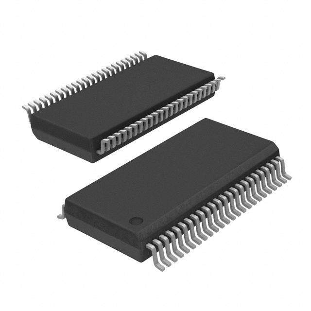
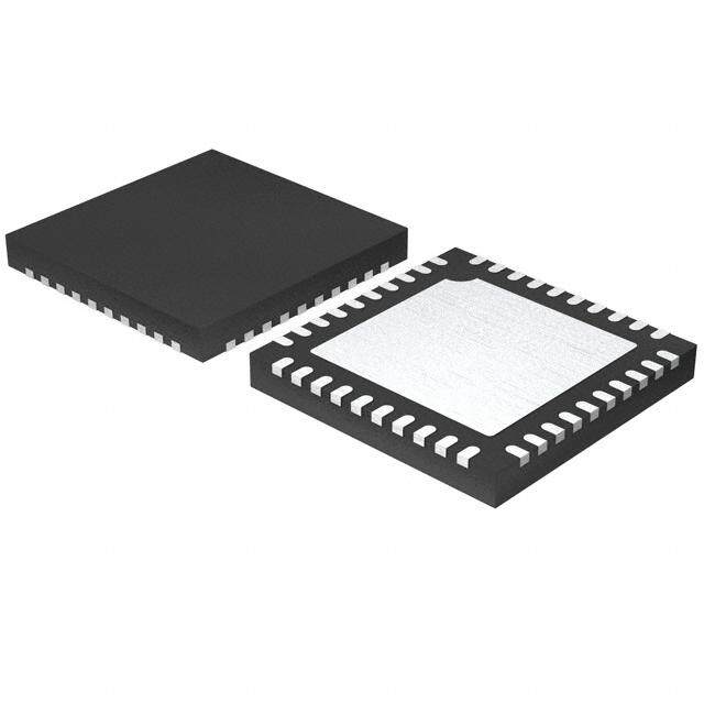
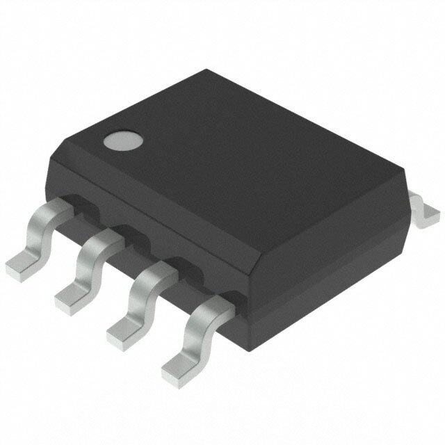
| 产品图片 |
|
| rohs | 符合RoHS无铅 / 符合限制有害物质指令(RoHS)规范要求 |
| 产品系列 | 数据转换器IC,模数转换器 - ADC,Maxim Integrated MAX1230BCTI+- |
| 数据手册 | |
| 产品型号 | MAX1230BCTI+ |
| 产品培训模块 | http://www.digikey.cn/PTM/IndividualPTM.page?site=cn&lang=zhs&ptm=25703http://www.digikey.cn/PTM/IndividualPTM.page?site=cn&lang=zhs&ptm=25705 |
| 产品目录页面 | |
| 产品种类 | 模数转换器 - ADC |
| 位数 | 12 |
| 供应商器件封装 | 28-TQFN (5x5) |
| 信噪比 | 70 dB |
| 分辨率 | 12 bit |
| 包装 | 管件 |
| 商标 | Maxim Integrated |
| 安装类型 | 表面贴装 |
| 安装风格 | SMD/SMT |
| 封装 | Tube |
| 封装/外壳 | 28-WFQFN 裸露焊盘 |
| 封装/箱体 | TQFN-28 |
| 工作温度 | 0°C ~ 70°C |
| 工作电源电压 | 4.75 V to 5.25 V |
| 工厂包装数量 | 60 |
| 接口类型 | Serial |
| 数据接口 | MICROWIRE™,QSPI™,串行,SPI™ |
| 最大功率耗散 | 1667 mW |
| 最大工作温度 | + 70 C |
| 最小工作温度 | 0 C |
| 标准包装 | 1 |
| 特性 | - |
| 电压参考 | Internal 4.096 V or External |
| 电压源 | 单电源 |
| 系列 | MAX1230B |
| 结构 | SAR |
| 转换器数 | 1 |
| 转换器数量 | 1 |
| 转换速率 | 300 kS/s |
| 输入数和类型 | 16 个单端,单极16 个单端,双极8 个差分,单极8 个差分,双极 |
| 输入类型 | Single-Ended/Differential |
| 通道数量 | 16 Channel/8 Channel |
| 采样率(每秒) | 300k |
| 零件号别名 | MAX1230B |











PDF Datasheet 数据手册内容提取
19-2852; Rev 5; 12/10 EVAALVUAAILTAIOBNL EKIT 12-Bit 300ksps ADCs with FIFO, Temp Sensor, Internal Reference General Description Features M The MAX1226/MAX1228/MAX1230 are serial 12-bit ana- (cid:2) Internal Temperature Sensor (±0.7°C Accuracy) A log-to-digital converters (ADCs) with an internal reference (cid:2) 16-Entry First-In/First-Out (FIFO) X and an internal temperature sensor. These devices fea- (cid:2) Analog Multiplexer with True Differential ture on-chip FIFO, scan mode, internal clock mode, inter- 1 Track/Hold nal averaging, and AutoShutdown™. The maximum 2 16-, 12-, 8-Channel Single Ended sampling rate is 300ksps using an external clock. The 2 8-, 6-, 4-Channel True Differential MAX1230 has 16 input channels, the MAX1228 has 12 6 input channels, and the MAX1226 has 8 input channels. (Unipolar or Bipolar) / All input channels are configurable for single-ended or (cid:2) Accuracy: ±1 LSB INL, ±1 LSB DNL, No Missing M differential inputs in unipolar or bipolar mode. All three Codes Over Temperature A devices operate from a +5V supply and contain a 10MHz (cid:2) Scan Mode, Internal Averaging, and Internal Clock SPI™/QSPI™/MICROWIRE™-compatible serial port. X (cid:2) Low-Power Single +5V Operation The MAX1230 is available in 28-pin 5mm x 5mm thin 2.3mA at 300ksps 1 QFN with exposed pad and 24-pin QSOP packages. (cid:2) Internal 4.096V Reference or External Differential 2 The MAX1226/MAX1228 are only available in QSOP Reference 2 packages. All three devices are specified over the extended -40°C to +85°C temperature range. (cid:2) 10MHz 3-Wire SPI/QSPI/MICROWIRE-Compatible 8 Interface / M ________________________Applications (cid:2) Space-Saving 28-Pin 5mm x 5mm Thin QFN A System Supervision Package Ordering Information X Data-Acquisition Systems 1 Industrial Control Systems PART TEMP RANGE PIN-PACKAGE 2 Patient Monitoring MAX1226BCEE+ 0°C to +70°C 16 QSOP 3 Data Logging MAX1226BEEE+ -40°C to +85°C 16 QSOP 0 Instrumentation MAX1228BCEP+ 0°C to +70°C 20 QSOP MAX1228BEEP+ -40°C to +85°C 20 QSOP +Denotes a lead(Pb)-free/RoHS-compliant package. AutoShutdown is a trademark of Maxim Integrated Products, Inc. *EP= Exposed pad (TQFN only). Connect to GND. SPI/QSPI are trademarks of Motorola, Inc. Ordering Information continued at end of data sheet. MICROWIRE is a trademark of National Semiconductor Corp. Pin Configurations TOP VIEW + AIN0 1 20 EOC + AIN0 1 16 EOC AIN1 2 19 DOUT AIN2 3 18 DIN AIN1 2 15 DOUT AIN3 4 17 CS AIN2 3 14 DIN AIN4 5 MAX1228 16 SCLK AIN3 4 MAX1226 13 CS AIN4 5 12 SCLK AIN5 6 15 VDD AIN6 7 14 GND AIN5 6 11 VDD AIN7 8 13 REF+ REF-/AIN6 7 10 GND AIN8 9 12 CNVST/AIN11 CNVST/AIN7 8 9 REF+ AIN9 10 11 REF-/AIN10 QSOP Pin Configurations continued at end of data sheet. QSOP ________________________________________________________________Maxim Integrated Products 1 For pricing, delivery, and ordering information,please contact Maxim Directat 1-888-629-4642, or visit Maxim’s website at www.maxim-ic.com.
12-Bit 300ksps ADCs with FIFO, Temp Sensor, Internal Reference 0 ABSOLUTE MAXIMUM RATINGS 3 VDDto GND..............................................................-0.3V to +6V Operating Temperature Ranges 2 CS, SCLK, DIN, EOC, DOUT to GND.........-0.3V to (VDD+ 0.3V) MAX12__C__.......................................................0°C to +70°C 1 AIN0–AIN13, REF-/AIN_, CNVST/AIN_, MAX12__E__....................................................-40°C to +85°C X REF+ to GND.........................................-0.3V to (VDD+ 0.3V) Storage Temperature Range.............................-60°C to +150°C Maximum Current into Any Pin............................................50mA Junction Temperature......................................................+150°C A Continuous Power Dissipation (TA= +70°C) Lead Temperature (soldering, 10s).................................+300°C 16-Pin QSOP (derate 8.3mW/°C above +70°C)...........667mW Soldering Temperature (reflow).......................................+260°C M 20-Pin QSOP (derate 9.1mW/°C above +70°C)...........727mW / 24-Pin QSOP (derate 9.5mW/°C above +70°C)...........762mW 8 28-Pin Thin QFN 5mm x 5mm 2 (derate 20.8mW/°C above +70°C)........................1667mW 2 Stresses beyond those listed under “Absolute Maximum Ratings” may cause permanent damage to the device. These are stress ratings only, and functional 1 operation of the device at these or any other conditions beyond those indicated in the operational sections of the specifications is not implied. Exposure to X absolute maximum rating conditions for extended periods may affect device reliability. A ELECTRICAL CHARACTERISTICS M (VDD= +5V ±5%, fSAMPLE= 300kHz, fSCLK= 4.8MHz (50% duty cycle), VREF= 4.096V, TA= TMINto TMAX, unless otherwise noted. Typical values are at TA= +25°C.) / 6 PARAMETER SYMBOL CONDITIONS MIN TYP MAX UNITS 2 DC ACCURACY (Note 1) 2 1 Resolution RES 12 Bits X Integral Nonlinearity INL ±1.0 LSB Differential Nonlinearity DNL No missing codes over temperature ±1.0 LSB A Offset Error ±0.5 ±4.0 LSB M Gain Error (Note 2) ±0.5 ±4.0 LSB Offset Error Temperature ppm/°C ±2 Coefficient FSR Gain Temperature Coefficient ±0.8 ppm/°C Channel-to-Channel Offset ±0.1 LSB Matching DYNAMIC SPECIFICATIONS (30kHz sine wave input, 4.096VP-P, 300ksps, fSCLK = 4.8MHz) Signal-to-Noise Plus Distortion SINAD 73 dB Total Harmonic Distortion THD Up to the 5th harmonic -88 dBc Spurious-Free Dynamic Range SFDR 89 dBc Intermodulation Distortion IMD fin1 = 29.9kHz, fin2 = 30.2kHz 76 dBc Full-Power Bandwidth -3dB point 1 MHz Full-Linear Bandwidth S / (N + D) > 68dB 100 kHz 2 _______________________________________________________________________________________
12-Bit 300ksps ADCs with FIFO, Temp Sensor, Internal Reference ELECTRICAL CHARACTERISTICS (continued) M (VDD= +5V ±5%, fSAMPLE= 300kHz, fSCLK= 4.8MHz (50% duty cycle), VREF= 4.096V, TA= TMINto TMAX, unless otherwise noted. A Typical values are at TA= +25°C.) X PARAMETER SYMBOL CONDITIONS MIN TYP MAX UNITS 1 CONVERSION RATE 2 External reference 0.8 2 Power-Up Time tPU µs Internal reference (Note 3) 65 6 Acquisition Time tACQ 0.6 µs /M Internally clocked 3.5 Conversion Time tCONV µs A Externally clocked (Note 4) 2.7 X Externally clocked conversion 0.1 4.8 External Clock Frequency fSCLK Data I/O 10 MHz 1 2 Aperture Delay 30 ns 2 Aperture Jitter <50 ps 8 ANALOG INPUT / Unipolar 0 VREF M Input Voltage Range V Bipolar (Note 5) -V R EF /2 VR EF /2 A Input Leakage Current VIN = VDD ±0.01 ±1 µA X Input Capacitance During acquisition time (Note 6) 24 pF 1 INTERNAL TEMPERATURE SENSOR 2 Measurement Error (Note 7) TA = +25°C ±0.7 °C 3 TA = TMIN to TMAX ±1.2 ±3.0 0 Temperature Measurement Noise 0.1 °CRMS Temperature Resolution 1/8 °C Power-Supply Rejection 0.3 °C/V INTERNAL REFERENCE REF Output Voltage 4.024 4.096 4.168 V REF Temperature Coefficient TCREF ±20 ppm/°C Output Resistance 6.5 kΩ REF Output Noise 200 µVRMS REF Power-Supply Rejection PSRR -70 dB EXTERNAL REFERENCE INPUT REF- Input Voltage Range VREF- 0 500 mV REF+ Input Voltage Range VREF+ 1.0 VDD + 50mV V VREF+ = 4.096V, fSAMPLE = 300ksps 40 100 REF+ Input Current IREF+ µA VREF+ = 4.096V, fSAMPLE = 0 ±0.1 ±5 _______________________________________________________________________________________ 3
12-Bit 300ksps ADCs with FIFO, Temp Sensor, Internal Reference 0 ELECTRICAL CHARACTERISTICS (continued) 3 (VDD= +5V ±5%, fSAMPLE= 300kHz, fSCLK= 4.8MHz (50% duty cycle), VREF= 4.096V, TA= TMINto TMAX, unless otherwise noted. 2 Typical values are at TA= +25°C.) 1 PARAMETER SYMBOL CONDITIONS MIN TYP MAX UNITS X DIGITAL INPUTS (SCLK, DIN, CS, CNVST) A Input Voltage Low VIL (Note 8) 0.8 V M Input Voltage High VIH 2.0 V 8/ Input Hysteresis VHYST 200 mV 2 Input Leakage Current IIN VIN = 0 or VDD ±0.01 ±1.0 µA 2 Input Capacitance CIN 15 pF 1 DIGITAL OUTPUTS (DOUT, EOC) X ISINK = 2mA 0.4 Output Voltage Low VOL V A ISINK = 4mA 0.8 M Output Voltage High VOH ISOURCE = 1.5mA VDD - 0.5 V Tri-State Leakage Current IL CS = VDD ±0.05 ±1 µA / 6 Tri-State Output Capacitance COUT CS = VDD 15 pF 2 POWER REQUIREMENTS 2 Supply Voltage VDD 4.75 5.25 V 1 During temp sense 2800 3200 X Internal fSAMPLE = 300ksps 2300 2550 A reference fSAMPLE = 0, REF on 1050 1350 M Supply Current (Note 9) IDD Shutdown 0.2 5 µA During temp sense 1800 2300 External fSAMPLE = 300ksps 1600 1700 reference Shutdown 0.2 5 Power-Supply Rejection PSR VDD = 4.75V to 5.25V; full-scale input ±0.2 ±1.4 mV Note 1: Tested at VDD= +5V, unipolar input mode. Note 2: Offset nulled. Note 3: Time for reference to power up and settle to within 1 LSB. Note 4: Conversion time is defined as the number of clock cycles multiplied by the clock period; clock has 50% duty cycle. Note 5: The operational input voltage range for each individual input of a differentially configured pair is from GND to VDD. The operational input voltage difference is from -VREF/2 to +VREF/2. Note 6: See Figure 3 (Input Equivalent Circuit) and the Sampling Errorvs. Source Impedancecurve in the Typical Operating Characterisitcssection. Note 7: Fast automated test, excludes self-heating effects. Note 8: When CNVSTis configured as a digital input, do not apply a voltage between VILand VIH. Note 9: Supply current is specified depending on whether an internal or external reference is used for voltage conversions. Temperature measurements always use the internal reference. 4 _______________________________________________________________________________________
12-Bit 300ksps ADCs with FIFO, Temp Sensor, Internal Reference TIMING CHARACTERISTICS (Figure 1) M A PARAMETER SYMBOL CONDITIONS MIN TYP MAX UNITS Externally clocked conversion 208 X SCLK Clock Period tCP ns Data I/O 100 1 SCLK Duty Cycle tCH 40 60 % 2 2 SCLK Fall to DOUT Transition tDOT CLOAD = 30pF 40 ns 6 CS Rise to DOUT Disable tDOD CLOAD = 30pF 40 ns / CS Fall to DOUT Enable tDOE CLOAD = 30pF 40 ns M DIN to SCLK Rise Setup tDS 40 ns A SCLK Rise to DIN Hold tDH 0 ns X CS Fall to SC L K Ris e Se tup Tim e tCSS0 40 ns 1 CS Fall - t o- SC L K Ho ld Tim e tCSH0 0 ns 2 CS Ri se-t o- SC L K Ris e Ho ld Tim e tCSH1 0 4 µs 2 CS Ri se-t o- SC L K Ris e Se tup Tim e tCSS1 40 ns 8 CKSEL = 00, CKSEL = 01 (temp sense) 40 ns CNVST Pulse Width tCSW /M CKSEL = 01 (voltage conversion) 1.4 µs t T S Temp sense 55 A CS or CNVST Rise to EOC Voltage conversion 7 µs X Low (Note 10) t R P Reference power-up 65 1 Note 10: This time is defined as the number of clock cycles needed for conversion multiplied by the clock period. If the internal refer- 2 ence needs to be powered up, the total time is additive. The internal reference is always used for temperature measurements. 3 0 Typical Operating Characteristics (VDD= +5V, VREF= +4.096V, fSCLK= 4.8MHz, CLOAD= 30pF, TA= +25°C, unless otherwise noted.) INTEGRAL NONLINEARITY DIFFERENTIAL NONLINEARITY vs. OUTPUT CODE vs. OUTPUT CODE SINAD vs. FREQUENCY INTEGRAL NONLINEARITY (LSB)---00000001........462024680 MAX1226/28/30 toc01 DIFFERENTIAL NONLINEARITY (LSB)---00000001........462024680 MAX1226/28/30 toc02 SINAD AMPLITUDE (dB) 1234567890000000000 MAX1226/28/30 toc03 -0.8 -0.8 10 -1.0 -1.0 0 0 1024 2048 3072 4096 0 1024 2048 3072 4096 0.1 1 10 100 1000 OUTPUT CODE OUTPUT CODE FREQUENCY (kHz) _______________________________________________________________________________________ 5
12-Bit 300ksps ADCs with FIFO, Temp Sensor, Internal Reference 0 Typical Operating Characteristics (continued) 3 (VDD= +5V, VREF= +4.096V, fSCLK= 4.8MHz, CLOAD= 30pF, TA= +25°C, unless otherwise noted.) 2 1 X SFDR vs. FREQUENCY SUPPLY CURRENT vs. SAMPLING RATE SUPPLY CURRENT vs. SUPPLY VOLTAGE 8/MA E (dB) 11802000 MAX1226/28/30 toc04 T (A)µ11020000 MAX1226/28/30 toc05 T (A)µ11125000 MAX1226/28/30 toc06 D N 800 N 2 U E E X12 SFDR AMPLIT 4600 SUPPLY CURR 600 SUPPLY CURR11015000 400 A 20 M 0 200 1000 0.1 1 10 100 1000 1 10 100 1000 4.75 4.85 4.95 5.05 5.15 5.25 / 6 FREQUENCY (kHz) SAMPLING RATE (ksps) SUPPLY VOLTAGE (V) 2 SHUTDOWN SUPPLY CURRENT 2 vs. SUPPLY VOLTAGE SUPPLY CURRENT vs. TEMPERATURE MAX1 Y CURRENT (A)µ 000...456 MAX1226/28/30 toc07 RENT (A)µ111223050000 fS = 300ksps MAX1226/28/30 toc08 N SUPPL 0.3 PLY CUR1150 DOW 0.2 SUP1100 T U SH 0.1 1050 0 1000 4.75 4.85 4.95 5.05 5.15 5.25 -40 -15 10 35 60 85 SUPPLY VOLTAGE (V) TEMPERATURE (°C) SHUTDOWN SUPPLY CURRENT INTERNAL REFERENCE VOLTAGE vs. TEMPERATURE vs. SUPPLY VOLTAGE Y CURRENT (A)µ 000...456 MAX1226/28/30 toc09 CE VOLTAGE (V) 444...000445990890 MAX1226/28/30 toc10 UPPL 0.3 EREN 4.0497 OWN S 0.2 AL REF 4.0496 D N T R U E SH 0.1 INT 4.0495 0 4.0494 -40 -15 10 35 60 85 4.75 4.85 4.95 5.05 5.15 5.25 TEMPERATURE (°C) SUPPLY VOLTAGE (V) 6 _______________________________________________________________________________________
12-Bit 300ksps ADCs with FIFO, Temp Sensor, Internal Reference Typical Operating Characteristics (continued) M (VDD= +5V, VREF= +4.096V, fSCLK= 4.8MHz, CLOAD= 30pF, TA= +25°C, unless otherwise noted.) A X INTERNAL REFERENCE VOLTAGE OFFSET ERROR OFFSET ERROR vs. TEMPERATURE vs. SUPPLY VOLTAGE vs. TEMPERATURE 1 RNAL REFERENCE VOLTAGE (V)4444....000055441098 MAX1226/28/30 toc11 OFFSET ERROR (LSB)-0000....10123 MAX1226/28/30 toc12 OFFSET ERROR (LSB)-0000....11023 MAX1226/28/30 toc13 226/MAX1 E T IN -0.2 -0.2 2 2 4.047 -0.3 -0.3 -40 -15 10 35 60 85 4.75 4.85 4.95 5.05 5.15 5.25 -40 -15 10 35 60 85 8 TEMPERATURE (°C) SUPPLY VOLTAGE (V) TEMPERATURE (°C) / M A GAIN ERROR vs. SUPPLY VOLTAGE GAIN ERROR vs. TEMPERATURE X N ERROR (LSB)-00..505 MAX1226/28/30 toc14 N ERROR (LSB)-00..055 MAX1226/28/30 toc15 1230 GAI GAI -1.0 -1.0 -1.5 -1.5 4.75 4.85 4.95 5.05 5.15 5.25 -40 -15 10 35 60 85 SUPPLY VOLTAGE (V) TEMPERATURE (°C) TEMPERATURE SENSOR ERROR SAMPLING ERROR vs. TEMPERATURE vs. SOURCE IMPEDANCE TURE SENSOR ERROR (C)°-10000.....50722005055 MAX1226/28/30 toc16 MPLING ERROR (LSB) ---62402 MAX1226/28/30 toc17 ERA-0.50 GRADE B SA P M E -8 T-0.75 -1.00 -10 -40 -15 10 35 60 85 0 2 4 6 8 10 TEMPERATURE (°C) SOURCE IMPEDANCE (kΩ) _______________________________________________________________________________________ 7
12-Bit 300ksps ADCs with FIFO, Temp Sensor, Internal Reference 0 Pin Description 3 2 MAX1230 MAX1230 MAX1228 MAX1226 NAME FUNCTION 1 TQFN QSOP X 1, 17, — — — N.C. No Connection. Not internally connected. A 19, 25 2–12, 26, M 1–14 — — AIN0–13 Analog Inputs 27, 28 / 8 — — 1–10 — AIN0–9 Analog Inputs 2 — — — 1–6 AIN0–5 Analog Inputs 2 Negative Input for External Differential Reference/Analog Input 14. 13 15 — — REF-/AIN14 1 See Table 3 for details on programming the setup register. X Negative Input for External Differential Reference/Analog Input 10. — — 11 — REF-/AIN10 A See Table 3 for details on programming the setup register. M Negative Input for External Differential Reference/Analog Input 6. — — — 7 REF-/AIN6 See Table 3 for details on programming the setup register. / 6 CNVST/ Active-Low Conversion Start Input/Analog Input 15. See Table 3 2 14 16 — — AIN15 for details on programming the setup register. 2 CNVST/ Active-Low Conversion Start Input/Analog Input 11. See Table 3 1 — — 12 — AIN11 for details on programming the setup register. X CNVST/ Active-Low Conversion Start Input/Analog Input 7. See Table 3 for A — — — 8 AIN7 details on programming the setup register. M 15 17 13 9 REF+ Positive Reference Input. Bypass to GND with a 0.1µF capacitor. 16 18 14 10 GND Ground 18 19 15 11 VDD Power Input. Bypass to GND with a 0.1µF capacitor. Serial Clock Input. Clocks data in and out of the serial interface. 20 20 16 12 SCLK (Duty cycle must be 40% to 60%.) See Table 3 for details on programming the clock mode. Active-Low Chip-Select Input. When CS is low, the serial interface 21 21 17 13 CS is enabled. When CS is high, DOUT is high impedance. Serial Data Input. DIN data is latched into the serial interface on 22 22 18 14 DIN the rising edge of SCLK. Serial Data Output. Data is clocked out on the falling edge of 23 23 19 15 DOUT SCLK. High impedance when CS is connected to VDD. 24 24 20 16 EOC End of Conversion Output. Data is valid after EOC pulls low. Exposed Pad. Internally connected to GND. Connect to a large — — — — EP ground plane to maximize thermal performance. Not intended as an electrical connection point. 8 _______________________________________________________________________________________
12-Bit 300ksps ADCs with FIFO, Temp Sensor, Internal Reference M CS A X tCSS0 tCH tCP tCSH1 tCSH0 1 tCSS1 2 2 SCLK 6 tDH tDS / M DIN A tDOT tDOD tDOE X DOUT 1 2 2 8 Figure 1. Detailed Serial-Interface Timing Diagram / M A CS DIN SERIAL INTERFACE DOUT X SCLK 1 2 OSCILLATOR CONTROL EOC 3 CNVST 0 AIN1 AIN2 12-BIT FIFO AND MUX SAR ACCUMULATOR ADC AIN15 TEMP SENSE REF- INTERNAL REF+ REFERENCE MAX1226 MAX1228 MAX1230 Figure 2. Functional Diagram Detailed Description configurations. Microprocessor (µP) control is made easy through a 3-wire SPI/QSPI/MICROWIRE-compati- The MAX1226/MAX1228/MAX1230 are low-power, seri- ble serial interface. al-output, multichannel ADCs with temperature-sensing capability for temperature-control, process-control, and Figure 2 shows a simplified functional diagram of the monitoring applications. These 12-bit ADCs have inter- MAX1226/MAX1228/MAX1230 internal architecture. nal track and hold (T/H) circuitry that supports single- The MAX1226 has eight single-ended analog input ended and fully differential inputs. Data is converted channels or four differential channels. The MAX1228 from an internal temperature sensor or analog voltage has 12 single-ended analog input channels or six differ- sources in a variety of channel and data-acquisition ential channels. The MAX1230 has 16 single-ended analog input channels or eight differential channels. _______________________________________________________________________________________ 9
12-Bit 300ksps ADCs with FIFO, Temp Sensor, Internal Reference 0 Converter Operation Tables 1–7 detail the register descriptions. Bits 5 and 4, 3 The MAX1226/MAX1228/MAX1230 ADCs use a fully dif- CKSEL1 and CKSEL0, respectively, control the clock 2 ferential, successive-approximation register (SAR) con- modes in the setup register (see Table 3). Choose 1 version technique and an on-chip T/H block to convert between four different clock modes for various ways to temperature and voltage signals into a 12-bit digital start a conversion and determine whether the acquisi- X result. Both single-ended and differential configurations tions are internally or externally timed. Select clock A are supported, with a unipolar signal range for single- mode 00 to configure CNVST/AIN_ to act as a conver- M ended mode and bipolar or unipolar ranges for differ- sion start and use it to request the programmed inter- ential mode. nally timed conversions without tying up the serial bus. / In clock mode 01, use CNVST to request conversions 8 Input Bandwidth one channel at a time, controlling the sampling speed 2 The ADC’s input-tracking circuitry has a 1MHz small- without tying up the serial bus. Request and start inter- 2 signal bandwidth, so it is possible to digitize high- nally timed conversions through the serial interface by 1 speed transient events and measure periodic signals writing to the conversion register in the default clock X with bandwidths exceeding the ADC’s sampling rate by mode, 10. Use clock mode 11 with SCLK up to 4.8MHz using undersampling techniques. Anti-alias prefiltering for externally timed acquisitions to achieve sampling A of the input signals is necessary to avoid high-frequen- rates up to 300ksps. Clock mode 11 disables scanning M cy signals aliasing into the frequency band of interest. and averaging. See Figures 4–7 for timing specifica- tions and how to begin a conversion. / Analog Input Protection 6 Internal ESD protection diodes clamp all pins to VDD These devices feature an active-low, end-of-conversion 2 and GND, allowing the inputs to swing from (GND - output. EOC goes low when the ADC completes the 2 0.3V) to (VDD + 0.3V) without damage. However, for last-requested operation and is waiting for the next input 1 accurate conversions near full scale, the inputs must data byte (for clock modes 00 and 10). In clock mode X not exceed VDD by more than 50mV or be lower than 01, EOC goes low after the ADC completes each GND by 50mV. If an off-channel analog input voltage requested operation. EOC goes high when CS or A exceeds the supplies, limit the input current to 2mA. CNVSTgoes low. EOCis always high in clock mode 11. M 3-Wire Serial Interface Single-Ended/Differential Input The MAX1226/MAX1228/MAX1230 feature a serial The MAX1226/MAX1228/MAX1230 use a fully differen- interface compatible with SPI/QSPI and MICROWIRE tial ADC for all conversions. The analog inputs can be devices. For SPI/QSPI, ensure the CPU serial interface configured for either differential or single-ended con- runs in master mode so it generates the serial clock versions by writing to the setup register (see Table 3). signal. Select the SCLK frequency of 10MHz or less, Single-ended conversions are internally referenced to and set clock polarity (CPOL) and phase (CPHA) in the GND (Figure 3). µP control registers to the same value. The MAX1226/ In differential mode, the T/H samples the difference MAX1228/MAX1230 operate with SCLK idling high or between two analog inputs, eliminating common-mode low, and thus operate with CPOL = CPHA = 0 or CPOL DC offsets and noise. IN+ and IN- are selected from = CPHA = 1. Set CS low to latch input data at DIN on the following pairs: AIN0/AIN1, AIN2/AIN3, AIN4/AIN5, the rising edge of SCLK. Output data at DOUT is AIN6/AIN7, AIN8/AIN9, AIN10/AIN11, AIN12/AIN13, updated on the falling edge of SCLK. Bipolar true dif- and AIN14/AIN15. AIN0–AIN7 are available on the ferential results and temperature sensor results are MAX1226, MAX1228, and MAX1230. AIN8–AIN11 are available in two’s complement format, while all others only available on the MAX1228 and MAX1230. are in binary. AIN12–AIN15 are only available on the MAX1230. See Serial communication always begins with an 8-bit input Tables 2–5 for more details on configuring the inputs. data byte (MSB first) loaded from DIN. Use a second For the inputs that can be configured as CNVST or an byte, immediately following the setup byte, to write to analog input, only one can be used at a time. For the the unipolar mode or bipolar mode registers (see inputs that can be configured as REF- or an analog Tables 1, 3, 4, and 5). A high-to-low transition on CSini- input, the REF- configuration excludes the analog input. tiates the data input operation. The input data byte and Unipolar/Bipolar the subsequent data bytes are clocked from DIN into Address the unipolar and bipolar registers through the the serial interface on the rising edge of SCLK. setup register (bits 1 and 0). Program a pair of analog channels for differential operation by writing a 1 to the 10 ______________________________________________________________________________________
12-Bit 300ksps ADCs with FIFO, Temp Sensor, Internal Reference where RIN = 1.5kΩ, RS is the source impedance of the M input signal, and tPWR = 1µs, the power-up time of the device. The varying power-up times are detailed in the A REF (SINAIGNL0E- AEINND1E5D); GND DAC explanation of the clock mode conversions. X AIN0, AIN2, tACQ is never less than 1.4µs, and any source imped- 1 AIN4…AIN14 (DIFFERENTIAL) CIN+ COMPARATOR ance below 300Ω does not significantly affect the 2 + ADC’s AC performance. A high-impedance source can 2 HOLD be accommodated either by lengthening tACQ or by 6 - placing a 1µF capacitor between the positive and neg- GND ative analog inputs. / CIN- M (SINGLE ENDED); AIN1, AIN3, Internal FIFO A AIN5…AIN15 (DIFFERENTIAL) HOLD HOLD The MAX1226/MAX1228/MAX1230 contain a FIFO X buffer that can hold up to 16 ADC results plus one tem- VDD/2 perature result. This allows the ADC to handle multiple 1 internally clocked conversions and a temperature mea- 2 surement, without tying up the serial bus. 2 Figure 3. Equivalent Input Circuit If the FIFO is filled and further conversions are request- 8 ed without reading from the FIFO, the oldest ADC / appropriate bit of the bipolar or unipolar register. results are overwritten by the new ADC results. Each M Unipolar mode sets the differential input range from 0 to result contains 2 bytes, with the MSB preceded by 4 A VREF. A negative differential analog input in unipolar leading zeros. After each falling edge of CS, the oldest mode causes the digital output code to be zero. available byte of data is available at DOUT, MSB first. X Selecting bipolar mode sets the differential input range When the FIFO is empty, DOUT is zero. 1 to ±VREF / 2. The digital output code is binary in unipo- The first 2 bytes of data read out after a temperature mea- 2 lar mode and two’s complement in bipolar mode. (See surement always contain the temperature result preceded 3 the transfer function graphs, Figures 8 and 9.) by 4 leading zeros, MSB first. If another temperature mea- 0 In single-ended mode, the MAX1226/MAX1228/ surement is performed before the first temperature result MAX1230 always operate in unipolar mode. The analog is read out, the old measurement is overwritten by the inputs are internally referenced to GND with a full-scale new result. Temperature results are in degrees Celsius input range from 0 to VREF. (two’s complement) at a resolution of 1/8 of degree. See the Temperature Measurementssection for details on True Differential Analog Input T/H converting the digital code to a temperature. The equivalent circuit of Figure 3 shows the MAX1226/MAX1228/MAX1230s’ input architecture. In Internal Clock track mode, a positive input capacitor is connected to The MAX1226/MAX1228/MAX1230 operate from an inter- AIN0–AIN15 in single-ended mode (and AIN0, AIN2, nal oscillator, which is accurate within 10% of the 4.4MHz AIN4…AIN14 in differential mode). A negative input nominal clock rate. The internal oscillator is active in clock capacitor is connected to GND in single-ended mode modes 00, 01, and 10. Read out the data at clock speeds (or AIN1, AIN3, AIN5…AIN15 in differential mode). For up to 10MHz. See Figures 4–7 for details on timing speci- external track-and-hold timing, use clock mode 01. fications and starting a conversion. After the T/H enters hold mode, the difference between Applications Information the sampled positive and negative input voltages is converted. The time required for the T/H to acquire an Register Descriptions input signal is determined by how quickly its input The MAX1226/MAX1228/MAX1230 communicate capacitance is charged. If the input signal’s source between the internal registers and the external circuitry impedance is high, the required acquisition time length- through the SPI-/QSPI-compatible serial interface. ens. The acquisition time, tACQ, is the maximum time Table 1 details the registers and the bit names. Tables needed for a signal to be acquired, plus the power-up 2–7 show the various functions within the conversion time. It is calculated by the following equation: register, setup register, averaging register, reset regis- ter, unipolar register, and bipolar register. tAQC = 9 x (RS + RIN) x 24pF + tPWR ______________________________________________________________________________________ 11
12-Bit 300ksps ADCs with FIFO, Temp Sensor, Internal Reference 0 Conversion Time Calculations In clock mode 01, the total conversion time depends on 3 The conversion time for each scan is based on a num- how long CNVST is held low or high, including any time 2 ber of different factors: conversion time per sample, required to turn on the internal reference. Conversion samples per result, results per scan, if a temperature time in externally clocked mode (CKSEL1, CKSEL0 = 11) 1 measurement is requested, and if the external refer- depends on the SCLK period and how long CS is held X ence is in use. high between each set of eight SCLK cycles. A Use the following formula to calculate the total conver- Conversion Register M sion time for an internally timed conversion in clock Select active analog input channels, scan modes, and modes 00 and 10 (see the Electrical Characteristics / a single temperature measurement per scan by writing 8 section as applicable): to the conversion register. Table 2 details channel 2 total conversion time = tcnv ✕navg x nresult+ tTS+ tRP selection, the four scan modes, and how to request a 2 temperature measurement. Request a scan by writing where: 1 to the conversion register when in clock mode 10 or 11, tcnv= tacq(max) + tconv(max) or by applying a low pulse to the CNVST pin when in X navg= samples per result (amount of averaging) clock mode 00 or 01. A nresult = number of FIFO results requested; determined A conversion is not performed if it is requested on a M by number of channels being scanned by NSCAN1, channel that has been configured as CNVST or REF-. NSCAN0 Do not request conversions on channels 8–15 on the / 6 tTS = time required for temperature measurement; set MAX1226 and channels 12–15 on the MAX1228. Set 2 to zero if temp measurement is not requested CHSEL3:CHSEL0 to the lower channel’s binary value. If 2 the last two channels are configured as a differential tRP = internal reference wake-up; set to zero if internal 1 reference is already powered up or external reference is pair and one of them has been reconfigured as CNVST or REF-, the pair is ignored. X being used A M Table 1. Input Data Byte (MSB First) REGISTER NAME BIT 7 BIT 6 BIT 5 BIT 4 BIT 3 BIT 2 BIT 1 BIT 0 Conversion 1 CHSEL3 CHSEL2 CHSEL1 CHSEL0 SCAN1 SCAN0 TEMP Setup 0 1 CKSEL1 CKSEL0 REFSEL1 REFSEL0 DIFFSEL1 DIFFSEL0 Averaging 0 0 1 AVGON NAVG1 NAVG0 NSCAN1 NSCAN0 Reset 0 0 0 1 RESET X X X Unipolar mode (setup) UCH0/1 UCH2/3 UCH4/5 UCH6/7 UCH8/9* UCH10/11* UCH12/13** UCH14/15** Bipolar mode (setup) BCH0/1 BCH1/2 BCH4/5 BCH6/7 BCH8/9* BCH10/11* BCH12/13** BCH14/15** *Unipolar/bipolar channels 8–15 are only valid on the MAX1228 and MAX1230. **Unipolar/bipolar channels 12–15 are only valid on the MAX1230. X = Don’t care. 12 ______________________________________________________________________________________
12-Bit 300ksps ADCs with FIFO, Temp Sensor, Internal Reference Table 2. Conversion Register* Select scan mode 00 or 01 to return one result per sin- M gle-ended channel and one result per differential pair within the requested range, plus one temperature result if A BIT BIT FUNCTION selected. Select scan mode 10 to scan a single input X NAME channel numerous times, depending on NSCAN1 and 1 — 7 (MSB) Set to 1 to select conversion register. NSCAN0 in the averaging register (Table 6). Select scan 2 CHSEL3 6 Analog input channel select. mode 11 to return only one result from a single channel. 2 CHSEL2 5 Analog input channel select. Setup Register 6 CHSEL1 4 Analog input channel select. Write a byte to the setup register to configure the clock, / CHSEL0 3 Analog input channel select. reference, and power-down modes. Table 3 details the M bits in the setup register. Bits 5 and 4 (CKSEL1 and SCAN1 2 Scan mode select. A CKSEL0) control the clock mode, acquisition and sam- SCAN0 1 Scan mode select. pling, and the conversion start. Bits 3 and 2 (REFSEL1 X Set to 1 to take a single temperature and REFSEL0) control internal or external reference use. 1 TEMP 0 (LSB) measurement. The first conversion result Bits 1 and 0 (DIFFSEL1 and DIFFSEL0) address the 2 of a scan contains temperature information. unipolar mode and bipolar mode registers and configure 2 the analog input channels for differential operation. *See below for bit details. 8 Unipolar/Bipolar Registers / SELECTED M CHSEL3 CHSEL2 CHSEL1 CHSEL0 The final 2 bits (LSBs) of the setup register control the CHANNEL (N) unipolar/bipolar mode address registers. Set bits 1 and A 0 0 0 0 AIN0 0 (DIFFSEL1 and DIFFSEL0) to 10 to write to the unipo- X lar mode register. Set bits 1 and 0 to 11 to write to the 0 0 0 1 AIN1 bipolar mode register. In both cases, the setup byte 1 0 0 1 0 AIN2 must be followed immediately by 1 byte of data written 2 0 0 1 1 AIN3 to the unipolar register or bipolar register. Hold CS low 3 0 1 0 0 AIN4 and run 16 SCLK cycles before pulling CS high. If the 0 last 2 bits of the setup register are 00 or 01, neither the 0 1 0 1 AIN5 unipolar mode register nor the bipolar mode register is 0 1 1 0 AIN6 written. Any subsequent byte is recognized as a new 0 1 1 1 AIN7 input data byte. See Tables 4 and 5 to program the 1 0 0 0 AIN8 unipolar and bipolar mode registers. 1 0 0 1 AIN9 If a channel is configured as both unipolar and bipolar, 1 0 1 0 AIN10 the unipolar setting takes precedence. In unipolar 1 0 1 1 AIN11 mode, AIN+ can exceed AIN- by up to VREF. The out- put format in unipolar mode is binary. In bipolar mode, 1 1 0 0 AIN12 either input can exceed the other by up to VREF / 2. The 1 1 0 1 AIN13 output format in bipolar mode is two's complement. 1 1 1 0 AIN14 Averaging Register 1 1 1 1 AIN15 Write to the averaging register to configure the ADC to average up to 32 samples for each requested result, SCAN MODE (CHANNEL N IS and to independently control the number of results SCAN1 SCAN0 SELECTED BY BITS CHSEL3–CHSEL0) requested for single-channel scans. 0 0 Scans channels 0 through N. Table 2 details the four scan modes available in the con- version register. All four scan modes allow averaging as Scans channels N through the highest 0 1 long as the AVGON bit, bit 4 in the averaging register, is numbered channel. set to 1. Select scan mode 10 to scan the same channel Sc ans channel N re pe atedl y . The avera gi ng multiple times. Clock mode 11 disables averaging. 1 0 re g is ter sets the numb e r of re sul ts. 1 1 No scan. Converts channel N once only. ______________________________________________________________________________________ 13
12-Bit 300ksps ADCs with FIFO, Temp Sensor, Internal Reference 0 Table 3. Setup Register* 3 2 BIT NAME BIT FUNCTION 1 — 7 (MSB) Set to zero to select setup register. X — 6 Set to 1 to select setup register. A CKSEL1 5 Clock mode and CNVST configuration. Resets to 1 at power-up. M CKSEL0 4 Clock mode and CNVST configuration. REFSEL1 3 Reference mode configuration. / 8 REFSEL0 2 Reference mode configuration. 2 DIFFSEL1 1 Unipolar/bipolar mode register configuration for differential mode. 2 DIFFSEL0 0 (LSB) Unipolar/bipolar mode register configuration for differential mode. 1 *See below for bit details. X A M CKSEL1 CKSEL0 CONVERSION CLOCK ACQUISITION/SAMPLING CNVST CONFIGURATION 0 0 Internal Internally timed CNVST / 6 0 1 Internal Externally timed through CNVST CNVST 2 1 0 Internal Internally timed AIN15/11/7 2 1 1 External (4.8MHz max) Externally timed through SCLK AIN15/11/7 1 X A REFSEL1 REFSEL0 VOLTAGE REFERENCE AutoShutdown REF- CONFIGURATION M 0 0 Internal Reference off after scan; need AIN14/10/6 wake-up delay. 0 1 External single ended Reference off; no wake-up delay. AIN14/10/6 Reference always on; no wake-up 1 0 Internal AIN14/10/6 delay. 1 1 External differential Reference off; no wake-up delay. REF- DIFFSEL1 DIFFSEL0 FUNCTION 0 0 No data follows the setup byte. Unipolar mode and bipolar mode registers remain unchanged. 0 1 No data follows the setup byte. Unipolar mode and bipolar mode registers remain unchanged. 1 0 One byte of data follows the setup byte and is written to the unipolar mode register. 1 1 One byte of data follows the setup byte and is written to the bipolar mode register. 14 ______________________________________________________________________________________
12-Bit 300ksps ADCs with FIFO, Temp Sensor, Internal Reference Reset Register subtracted from the first at 68µA to calculate a digital M Write to the reset register (as shown in Table 7) to clear value that is proportional to absolute temperature. The the FIFO or to reset all registers to their default states. output data appearing at DOUT is the above digital A Set the RESET bit to 1 to reset the FIFO. Set the reset code minus an offset to adjust from Kelvin to Celsius. X bit to zero to return the MAX1226/MAX1228/MAX1230 The reference voltage used for the temperature mea- 1 to its default power-up state. surements is derived from the internal reference source 2 to ensure a resolution of 1/8 of a degree. Power-Up Default State 2 The MAX1226/MAX1228/MAX1230 power up with all Output Data Format 6 blocks in shutdown, including the reference. All registers Figures 4–7 illustrate the conversion timing for the / power up in state 00000000, except for the setup regis- M MAX1226/MAX1228/MAX1230. The 12-bit conversion ter, which powers up in clock mode 10 (CKSEL1 = 1). result is output in MSB-first format with 4 leading zeros. A DIN data is latched into the serial interface on the rising Temperature Measurements X edge of SCLK. Data on DOUT transitions on the falling The MAX1226/MAX1228/MAX1230 perform tempera- edge of SCLK. Conversions in clock modes 00 and 01 1 ture measurements with an internal diode-connected transistor. The diode bias current changes from 68µA are initiated by CNVST. Conversions in clock modes 10 2 to 4µA to produce a temperature-dependent bias volt- and 11 are initiated by writing an input data byte to the 2 conversion register. Data is binary for unipolar mode and age difference. The second conversion result at 4µA is 8 two’s complement for bipolar mode. / M Table 4. Unipolar Mode Register (Addressed Through Setup Register) A X BIT NAME BIT FUNCTION 1 UCH0/1 7 (MSB) Set to 1 to configure AIN0 and AIN1 for unipolar differential conversion. 2 UCH2/3 6 Set to 1 to configure AIN2 and AIN3 for unipolar differential conversion. 3 UCH4/5 5 Set to 1 to configure AIN4 and AIN5 for unipolar differential conversion. 0 UCH6/7 4 Set to 1 to configure AIN6 and AIN7 for unipolar differential conversion. UCH8/9 3 Set to 1 to configure AIN8 and AIN9 for unipolar differential conversion (MAX1228/MAX1230 only). UCH10/11 2 Set to 1 to configure AIN10 and AIN11 for unipolar differential conversion (MAX1228/MAX1230 only). UCH12/13 1 Set to 1 to configure AIN12 and AIN13 for unipolar differential conversion (MAX1230 only). UCH14/15 0 (LSB) Set to 1 to configure AIN14 and AIN15 for unipolar differential conversion (MAX1230 only). Table 5. Bipolar Mode Register (Addressed Through Setup Register) BIT NAME BIT FUNCTION BCH0/1 7 (MSB) Set to 1 to configure AIN0 and AIN1 for bipolar differential conversion. BCH2/3 6 Set to 1 to configure AIN2 and AIN3 for bipolar differential conversion. BCH4/5 5 Set to 1 to configure AIN4 and AIN5 for bipolar differential conversion. BCH6/7 4 Set to 1 to configure AIN6 and AIN7 for bipolar differential conversion. BCH8/9 3 Set to 1 to configure AIN8 and AIN9 for bipolar differential conversion (MAX1228/MAX1230 only). BCH10/11 2 Set to 1 to configure AIN10 and AIN11 for bipolar differential conversion (MAX1228/MAX1230 only). BCH12/13 1 Set to 1 to configure AIN12 and AIN13 for bipolar differential conversion (MAX1230 only). BCH14/15 0 (LSB) Set to 1 to configure AIN14 and AIN15 for bipolar differential conversion (MAX1230 only). ______________________________________________________________________________________ 15
12-Bit 300ksps ADCs with FIFO, Temp Sensor, Internal Reference 0 Table 6. Averaging Register* 3 2 BIT NAME BIT FUNCTION 1 — 7 (MSB) Set to zero to select averaging register. X — 6 Set to zero to select averaging register. A — 5 Set to 1 to select averaging register. M AVGON 4 Set to 1 to turn averaging on. Set to zero to turn averaging off. NAVG1 3 Configures the number of conversions for single-channel scans. / 8 NAVG0 2 Configures the number of conversions for single-channel scans. 2 NSCAN1 1 Single-channel scan count. (Scan mode 10 only.) 2 NSCAN0 0 (LSB) Single-channel scan count. (Scan mode 10 only.) 1 X *See below for bit details. A AVGON NAVG1 NAVG0 FUNCTION M 0 x x Performs 1 conversion for each requested result. / 6 1 0 0 Performs 4 conversions and returns the average for each requested result. 2 1 0 1 Performs 8 conversions and returns the average for each requested result. 2 1 1 0 Performs 16 conversions and returns the average for each requested result. 1 1 1 1 Performs 32 conversions and returns the average for each requested result. X A NSCAN1 NSCAN0 FUNCTION (APPLIES ONLY IF SCAN MODE 10 IS SELECTED) M 0 0 Scans channel N and returns 4 results. 0 1 Scans channel N and returns 8 results. 1 0 Scans channel N and returns 12 results. 1 1 Scans channel N and returns 16 results. Table 7. Reset Register BIT NAME BIT FUNCTION — 7 (MSB) Set to zero to select reset register. — 6 Set to zero to select reset register. — 5 Set to zero to select reset register. — 4 Set to 1 to select reset register. RESET 3 Set to zero to reset all registers. Set to 1 to clear the FIFO only. x 2 Reserved. Don’t care. x 1 Reserved. Don’t care. x 0 (LSB) Reserved. Don’t care. 16 ______________________________________________________________________________________
12-Bit 300ksps ADCs with FIFO, Temp Sensor, Internal Reference Internally Timed Acquisitions and erence needs to wake up, an additional 65µs is M Conversions Using CNVST required for the internal reference to power up. If a tem- perature measurement is being requested, reference A Performing Conversions in Clock Mode 00 power-up and temperature measurement are internally X In clock mode 00, the wake up, acquisition, conversion, timed. In this case, hold CNVSTlow for at least 40ns. and shutdown sequences are initiated through CNVST 1 and performed automatically using the internal oscilla- Set CNVST high to begin a conversion. After the con- 2 tor. Results are added to the internal FIFO to be read version is complete, the ADC shuts down and pulls 2 out later. See Figure 4 for clock mode 00 timing. EOC low. EOC stays low until CS or CNVST is pulled 6 low again. Wait until EOCgoes low before pulling CSor Initiate a scan by setting CNVST low for at least 40ns CNVSTlow. / before pulling it high again. The MAX1226/MAX1228/ M MAX1230 then wake up, scan all requested channels, If averaging is turned on, multiple CNVST pulses need A store the results in the FIFO, and shut down. After the to be performed before a result is written to the FIFO. scan is complete, EOCis pulled low and the results are Once the proper number of conversions has been per- X available in the FIFO. Wait until EOC goes low before formed to generate an averaged FIFO result, as speci- 1 pulling CSlow to communicate with the serial interface. fied by the averaging register, the scan logic 2 EOCstays low until CSor CNVSTis pulled low again. A automatically switches the analog input multiplexer to 2 temperature measurement result, if requested, pre- the next-requested channel. If a temperature measure- cedes all other FIFO results. ment is programmed, it is performed after the first rising 8 edge of CNVST following the input data byte written to / Do not initiate a second CNVST before EOC goes low; M the conversion register. The result is available on DOUT otherwise the FIFO can become corrupted. once EOChas been pulled low. A Externally Timed Acquisitions and Internally Timed Acquisitions and X Internally Timed Conversions with CNVST Conversions Using the Serial Interface 1 Performing Conversions in Clock Mode 01 Performing Conversions in Clock Mode 10 2 In clock mode 01, conversions are requested one at a In clock mode 10, the wake-up, acquisition, conversion, 3 time using CNVSTand performed automatically using the and shutdown sequences are initiated by writing an 0 internal oscillator. See Figure 5 for clock mode 01 timing. input data byte to the conversion register, and are per- Setting CNVSTlow begins an acquisition, wakes up the formed automatically using the internal oscillator. This ADC, and places it in track mode. Hold CNVST low for is the default clock mode upon power-up. See Figure 6 at least 1.4µs to complete the acquisition. If internal ref- for clock mode 10 timing. CNVST (UP TO 514 INTERNALLY CLOCKED ACQUISITIONS AND CONVERSIONS) CS SCLK DOUT MSB1 LSB1 MSB2 EOC SET CNVST LOW FOR AT LEAST 40ns TO BEGIN A CONVERSION. Figure 4. Clock Mode 00 ______________________________________________________________________________________ 17
12-Bit 300ksps ADCs with FIFO, Temp Sensor, Internal Reference 0 3 CNVST 2 (CONVERSION2) 1 (ACQUISITION1) (ACQUISITION2) X CS A (CONVERSION1) M SCLK / 8 DOUT 2 MSB1 LSB1 MSB2 2 1 EOC X A REQUEST MULTIPLE CONVERSIONS BY SETTING CNVST LOW FOR EACH CONVERSION. M Figure 5. Clock Mode 01 / 6 2 2 (CONVERSION BYTE) 1 DIN X (UP TO 514 INTERNALLY CLOCKED ACQUISITIONS AND CONVERSIONS) A CS M SCLK DOUT MSB1 LSB1 MSB2 EOC THE CONVERSION BYTE BEGINS THE ACQUISITION. CNVST IS NOT REQUIRED. Figure 6. Clock Mode 10 Initiate a scan by writing a byte to the conversion regis- Externally Clocked Acquisitions and ter. The MAX1226/MAX1228/MAX1230 then power up, Conversions Using the Serial Interface scan all requested channels, store the results in the Performing Conversions in Clock Mode 11 FIFO, and shut down. After the scan is complete, EOC In clock mode 11, acquisitions and conversions are ini- is pulled low and the results are available in the FIFO. If tiated by writing to the conversion register and are per- a temperature measurement is requested, the tempera- formed one at a time using the SCLK as the conversion ture result precedes all other FIFO results. EOC stays clock. Scanning and averaging are disabled, and the low until CSis pulled low again. conversion result is available at DOUT during the con- version. SeeFigure 7 for clock mode 11 timing. 18 ______________________________________________________________________________________
12-Bit 300ksps ADCs with FIFO, Temp Sensor, Internal Reference M A DIN (CONVERSION BYTE) X (ACQUISITION1) (CONVERSION1) (ACQUISITION2) 1 CS 2 2 SCLK 6 / M DOUT A MSB1 LSB1 MSB2 X EOC 1 2 EXTERNALLY TIMED ACQUISITION, SAMPLING AND CONVERSION WITHOUT CNVST. 2 8 Figure 7. Clock Mode 11 / M Initiate a conversion by writing a byte to the conversion Transfer Function A register followed by 16 SCLK cycles. If CS is pulsed Figure 8 shows the unipolar transfer function for single- high between the eighth and ninth cycles, the pulse ended or differential inputs. Figure 9 shows the bipolar X width must be less than 100µs. To continuously con- transfer function for differential inputs. Code transitions 1 vert at 16 cycles per conversion, alternate 1 byte of occur halfway between successive-integer LSB values. 2 zeros between each conversion byte. Output coding is binary, with 1 LSB = VREF / 4096V for 3 unipolar and bipolar operation, and 1 LSB = 0.125°C If reference mode 00 is requested, or if an external ref- 0 for temperature measurements. erence is selected but a temperature measurement is being requested, wait 65µs with CS high after writing Layout, Grounding, and Bypassing the conversion byte to extend the acquisition and allow For best performance, use PC boards. Do not use wire- the internal reference to power up. To perform a tem- wrap boards. Board layout should ensure that digital perature measurement, write 24 bytes (192 cycles) of and analog signal lines are separated from each other. zeros after the conversion byte. The temperature result Do not run analog and digital (especially clock) signals appears on DOUT during the last 2 bytes of the parallel to one another or run digital lines underneath the 192 cycles. MAX1226/MAX1228/MAX1230 package. High-frequen- Partial Reads and Partial Writes cy noise in the VDD power supply can affect perfor- If the first byte of an entry in the FIFO is partially read mance. Bypass the VDD supply with a 0.1µF capacitor (CS is pulled high after fewer than eight SCLK cycles), to GND, close to the VDD pin. Minimize capacitor lead lengths for best supply-noise rejection. If the power sup- the second byte of data that is read out contains the next 8 bits (not b7–b0). The remaining bits are lost for ply is very noisy, connect a 10Ω resistor in series with the supply to improve power-supply filtering. For the that entry. If the first byte of an entry in the FIFO is read QFN package, connect its exposed pad to ground. out fully, but the second byte is read out partially, the rest of the entry is lost. The remaining data in the FIFO Definitions is uncorrupted and can be read out normally after tak- ing CS low again, as long as the 4 leading bits (nor- Integral Nonlinearity mally zeros) are ignored. Internal registers that are Integral nonlinearity (INL) is the deviation of the values written partially through the SPI contain new values, on an actual transfer function from a straight line. This starting at the MSB up to the point that the partial write straight line can be either a best-straight-line fit or a is stopped. The part of the register that is not written line drawn between the end points of the transfer func- contains previously written values. If CS is pulled low tion, once offset and gain errors have been nullified. before EOC goes low, a conversion cannot be com- INL for the MAX1226/MAX1228/MAX1230 is measured pleted and the FIFO is corrupted. using the end-point method. ______________________________________________________________________________________ 19
12-Bit 300ksps ADCs with FIFO, Temp Sensor, Internal Reference 0 OUTPUT CODE 3 OUTPUT CODE 2 1 11 . . . 111 FTURLALN-SSICTIAOLNE 011 . . . 111 FS = VR2EF + VCOM X 011 . . . 110 ZS = COM 11 . . . 110 A 11 . . . 101 -FS = -VREF + VC OM 000 . . . 010 2 M 000 . . . 001 1 LSB = VREF 4096 8/ FS = VREF + VCOM 000 . . . 000 111 . . . 111 2 ZS = VCOM 111 . . . 110 2 1 LSB = VREF 4096 111 . . . 101 1 00 . . . 011 X 00 . . . 010 100 . . . 001 A 00 . . . 001 100 . . . 000 00 . . . 000 M 0 1 2 3 FS - FS COM* +FS - 1 LSB / (COM) 6 INPUT VOLTAGE (LSB) FS - 3/2 LSB INPUT VOLTAGE (LSB) 2 *VCOM ≥ VREF / 2 2 Figure 8. Unipolar Transfer Function, Full Scale (FS) = VREF Figure 9. Bipolar Transfer Function, Full Scale (±FS) = ±VREF/ 2 1 X Differential Nonlinearity In reality, there are other noise sources besides quanti- A Differential nonlinearity (DNL) is the difference between zation noise, including thermal noise, reference noise, M an actual step width and the ideal value of 1 LSB. A clock jitter, etc. Therefore, SNR is calculated by taking DNL error specification of less than 1 LSB guarantees the ratio of the RMS signal to the RMS noise, which no missing codes and a monotonic transfer function. includes all spectral components minus the fundamen- tal, the first five harmonics, and the DC offset. Aperture Jitter Aperture jitter (tAJ) is the sample-to-sample variation in Signal-to-Noise Plus Distortion the time between the samples. Signal-to-noise plus distortion (SINAD) is the ratio of the fundamental input frequency’s RMS amplitude to the Aperture Delay RMS equivalent of all other ADC output signals: Aperture delay (tAD) is the time between the rising edge of the sampling clock and the instant when an SINAD (dB) = 20 x log (SignalRMS/ NoiseRMS) actual sample is taken. Effective Number of Bits Effective number of bits (ENOB) indicates the global Signal-to-Noise Ratio accuracy of an ADC at a specific input frequency and For a waveform perfectly reconstructed from digital sampling rate. An ideal ADC error consists of quantiza- samples, signal-to-noise ratio (SNR) is the ratio of the tion noise only. With an input range equal to the full- full-scale analog input (RMS value) to the RMS quanti- scale range of the ADC, calculate the effective number zation error (residual error). The ideal, theoretical mini- of bits as follows: mum analog-to-digital noise is caused by quantization error only and results directly from the ADC’s resolution ENOB = (SINAD - 1.76) / 6.02 (N bits): SNR = (6.02 x N + 1.76)dB 20 ______________________________________________________________________________________
12-Bit 300ksps ADCs with FIFO, Temp Sensor, Internal Reference Total Harmonic Distortion where V1 is the fundamental amplitude, and V2–V5 are M Total harmonic distortion (THD) is the ratio of the RMS the amplitudes of the first five harmonics. A sum of the first five harmonics of the input signal to the Spurious-Free Dynamic Range fundamental itself. This is expressed as: X Spurious-free dynamic range (SFDR) is the ratio of the 1 RMS amplitude of the fundamental (maximum signal THD = 20 x log ⎛⎝⎜ (V22 + V32 + V42 + V52) / V1⎞⎠⎟ ctioonm cpoomnepnotn) eton tt.he RMS value of the next-largest distor- 22 6 / M A X 1 2 2 8 Pin Configurations (continued) / M TOP VIEW A AIN2 AIN1 AIN0 N.C. EOC DOUT DIN X + 1 AIN0 1 24 EOC 8 7 6 5 4 3 2 + 2 2 2 2 2 2 2 2 AIN1 2 23 DOUT N.C. 1 21 CS 3 AIN2 3 22 DIN 0 AIN3 2 20 SCLK AIN3 4 21 CS AIN4 5 MAX1230 20 SCLK AIN4 3 19 N.C. AIN5 6 19 VDD AIN5 4 MAX1230 18 VDD AIN6 7 18 GND AIN6 5 17 N.C. AIN7 8 17 REF+ AIN7 6 16 GND AIN8 9 16 CNVST/AIN15 EP AIN8 7 15 REF+ AIN9 10 15 REF-/AIN14 AIN10 11 14 AIN13 8 9 10 11 12 13 14 9 0 1 2 3 4 5 AIN11 12 13 AIN12 AIN AIN AIN AIN AIN AIN AIN QSOP REF-/ NVST/ C TQFN ______________________________________________________________________________________ 21
12-Bit 300ksps ADCs with FIFO, Temp Sensor, Internal Reference 0 Ordering Information (continued) Package Information 3 For the latest package outline information and land patterns 2 PART TEMP RANGE PIN-PACKAGE (footprints), go to www.maxim-ic.com/packages. Note that a 1 MAX1230BCEG+ 0°C to +70°C 24 QSOP “+”, “#”, or “-” in the package code indicates RoHS status only. X MAX1230BEEG+ -40°C to +85°C 24 QSOP Package drawings may show a different suffix character, but the drawing pertains to the package regardless of RoHS status. A MAX1230BCTI+ 0°C to +70°C 28 TQFN MAX1230BETI+ -40°C to +85°C 28 TQFN PACKAGE PACKAGE OUTLINE LAND M TYPE CODE NO. PATTERN NO +Denotes a lead(Pb)-free/RoHS-compliant package. / 16 QSOP E16+1 21-0055 90-0167 8 20 QSOP E20+1 21-0055 90-0168 2 24 QSOP E24+1 21-0055 90-0172 2 1 Chip Information 28 TQFN T2855+6 21-0140 90-0026 X PROCESS: BiCMOS A M / 6 2 2 1 X A M 22 ______________________________________________________________________________________
12-Bit 300ksps ADCs with FIFO, Temp Sensor, Internal Reference Revision History M A REVISION REVISION NUMBER DATE DESCRIPTION PAGES CHANGED X 1 Removed the A grade products from the Ordering Information table and 3 2/10 1, 3, 21 Electrical Characteristics table 2 2 Added lead-free information to Ordering Information and Package 4 8/10 1, 2, 21 6 Information sections; corrected soldering temperature / 5 12/10 Data sheet specifications changed 1–5, 7, 9, 22 M A X 1 2 2 8 / M A X 1 2 3 0 Maxim cannot assume responsibility for use of any circuitry other than circuitry entirely embodied in a Maxim product. No circuit patent licenses are implied. Maxim reserves the right to change the circuitry and specifications without notice at any time. Maxim Integrated Products, 120 San Gabriel Drive, Sunnyvale, CA 94086 408-737-7600 ____________________23 © 2010 Maxim Integrated Products Maxim is a registered trademark of Maxim Integrated Products, Inc.
Mouser Electronics Authorized Distributor Click to View Pricing, Inventory, Delivery & Lifecycle Information: M axim Integrated: MAX1228BCEP+ MAX1230BCTI+ MAX1226BCEE+ MAX1228BEEP+ MAX1230BEEG+ MAX1230BETI+ MAX1226BCEE+T MAX1228BCEP+T MAX1228BEEP+T MAX1230BCEG+ MAX1230BCEG+T MAX1230BCTI+T MAX1230BEEG+T MAX1230BETI+T MAX1226BEEE+