ICGOO在线商城 > MAX4782ETE+

 Datasheet下载
- 型号: MAX4782ETE+
- 制造商: Maxim
- 库位|库存: xxxx|xxxx
- 要求:
| 数量阶梯 | 香港交货 | 国内含税 |
| +xxxx | $xxxx | ¥xxxx |
查看当月历史价格
查看今年历史价格
MAX4782ETE+产品简介:
ICGOO电子元器件商城为您提供MAX4782ETE+由Maxim设计生产,在icgoo商城现货销售,并且可以通过原厂、代理商等渠道进行代购。 提供MAX4782ETE+价格参考以及MaximMAX4782ETE+封装/规格参数等产品信息。 你可以下载MAX4782ETE+参考资料、Datasheet数据手册功能说明书, 资料中有MAX4782ETE+详细功能的应用电路图电压和使用方法及教程。
MAX4782ETE+是Maxim Integrated生产的一款低导通电阻、双通道单刀双掷(SPDT)模拟开关,属于接口类中的模拟开关/多路复用器产品。该器件采用TQFN封装,具有低功耗、高带宽和快速开关速度的特点,适用于便携式和高性能系统。

典型应用场景包括:
1. 便携式设备音频切换:在智能手机、平板电脑或PDA中用于切换耳机与扬声器之间的音频信号,实现音频路径的灵活控制。
2. 电池供电系统:因其低导通电压和低静态电流,适合用于对功耗敏感的电池供电设备,如手持仪器和无线传感器。
3. 信号路由与多路复用:在数据采集系统中,用于选择不同传感器输入信号,实现多路模拟信号的切换与传输。
4. 通信系统接口:可用于通信设备中射频或基带信号的路径切换,提升系统集成度与响应速度。
5. 医疗电子设备:在便携式医疗监测仪中用于切换不同生物电信号(如心电、肌电)输入通道。

MAX4782ETE+工作电压范围为1.8V至5.5V,兼容多种逻辑电平,且具备良好的信号完整性,支持高达100MHz的信号带宽,可满足高速模拟信号切换需求。其小尺寸封装也便于在空间受限的高密度PCB设计中使用。综上,该器件广泛应用于消费电子、工业控制、通信及医疗等领域中需要高效模拟信号管理的场合。
| 参数 | 数值 |
| 产品目录 | 集成电路 (IC)半导体 |
| 描述 | IC MULTIPLEXER DUAL 4X1 16TQFN多路器开关 IC 4:1 2Ch Low Voltage Analog MUX |
| 产品分类 | |
| 品牌 | Maxim Integrated |
| 产品手册 | |
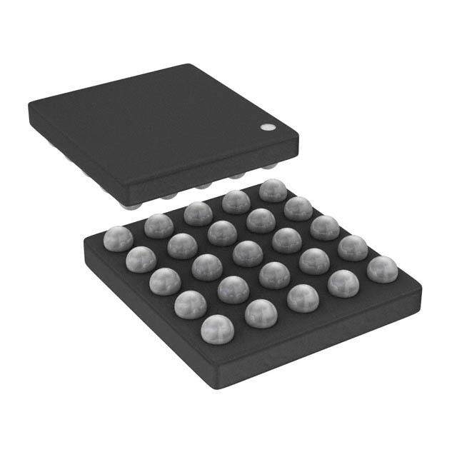
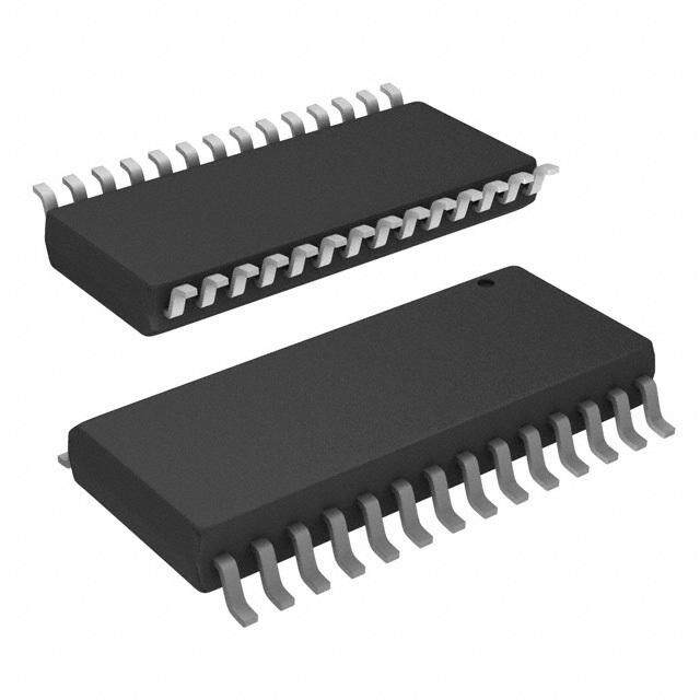
| 产品图片 |
|
| rohs | 符合RoHS无铅 / 符合限制有害物质指令(RoHS)规范要求 |
| 产品系列 | 开关 IC,多路器开关 IC,Maxim Integrated MAX4782ETE+- |
| 数据手册 | |
| 产品型号 | MAX4782ETE+ |
| 产品培训模块 | http://www.digikey.cn/PTM/IndividualPTM.page?site=cn&lang=zhs&ptm=25703http://www.digikey.cn/PTM/IndividualPTM.page?site=cn&lang=zhs&ptm=25705 |
| 产品种类 | 多路器开关 IC |
| 传播延迟时间 | 25 ns |
| 供应商器件封装 | 16-TQFN-EP(3x3) |
| 功能 | 多路复用器 |
| 包装 | 管件 |
| 商标 | Maxim Integrated |
| 安装类型 | 表面贴装 |
| 安装风格 | SMD/SMT |
| 导通电阻 | 1 欧姆 |
| 导通电阻—最大值 | 2.5 Ohms |
| 封装 | Tube |
| 封装/外壳 | 16-WFQFN 裸露焊盘 |
| 封装/箱体 | TQFN-EP-16 |
| 工作温度 | -40°C ~ 85°C |
| 工作电源电压 | 3 V |
| 工作电源电流 | 0.001 mA |
| 工厂包装数量 | 100 |
| 应用说明 | |
| 开关数量 | 2 |
| 最大功率耗散 | 1349 mW |
| 最大工作温度 | + 85 C |
| 最小工作温度 | - 40 C |
| 标准包装 | 1 |
| 电压-电源,单/双 (±) | 1.6 V ~ 3.6 V |
| 电压源 | 单电源 |
| 电流-电源 | 1µA |
| 电路 | 2 x 4:1 |
| 空闲时间—最大值 | 20 ns |
| 系列 | MAX4782 |
| 运行时间—最大值 | 30 ns |
| 通道数量 | 2 Channel |
| 零件号别名 | MAX4782 |









- 商务部:美国ITC正式对集成电路等产品启动337调查
- 曝三星4nm工艺存在良率问题 高通将骁龙8 Gen1或转产台积电
- 太阳诱电将投资9.5亿元在常州建新厂生产MLCC 预计2023年完工
- 英特尔发布欧洲新工厂建设计划 深化IDM 2.0 战略
- 台积电先进制程称霸业界 有大客户加持明年业绩稳了
- 达到5530亿美元!SIA预计今年全球半导体销售额将创下新高
- 英特尔拟将自动驾驶子公司Mobileye上市 估值或超500亿美元
- 三星加码芯片和SET,合并消费电子和移动部门,撤换高东真等 CEO
- 三星电子宣布重大人事变动 还合并消费电子和移动部门
- 海关总署:前11个月进口集成电路产品价值2.52万亿元 增长14.8%



PDF Datasheet 数据手册内容提取
19-2522; Rev 3; 2/05 Ω High-Speed, Low-Voltage, 0.7 CMOS Analog Switches/Multiplexers General Description Features M The MAX4781/MAX4782/MAX4783 are high-speed, ♦ On-Resistance A low-voltage, low on-resistance, CMOS analog multiplex- 0.7Ω(+3V Supply) ers/switches configured as an 8-channel multiplexer 1.6Ω(+1.8V Supply) X (MAX4781), two 4-channel multiplexers (MAX4782), ♦ On-Resistance Match Between Channels 4 and three single-pole/double-throw (SPDT) switches 0.3Ω(+3V Supply) 7 (MAX4783). ♦ On-Resistance Flatness 8 These devices operate with a +1.6V to +3.6V single 0.1Ω(+3V Supply) 1 supply. When powered from a +3V supply, MAX4781/ ♦ Single-Supply Operation Down to 1.6V / MAX4782/MAX4783 feature a 0.7Ω on-resistance M ♦ High-Current Handling Capacity (150mA 0(R.1OΩN),R wOiNth f0la.3tnΩesRsO.N Tmheastceh dinegv biceetws eheann cdhlea nrnaeil-lsto, -arnadil Continuous) A analog signals while consuming less than 3µW of qui- ♦ +1.8V CMOS-Logic Compatible X escent power. They are available in space-saving 16- ♦ Fast Switching Times: tON= 11ns, tOFF= 4ns 4 pin thin QFN (3mm x 3mm) and TSSOP packages. ♦ Pin Compatible with Industry-Standard 7 74HC4051/74HC4052/74HC4053 and 8 MAX4617/MAX4618/MAX4619 2 ♦ Available in 3mm x 3mm 16-Pin Thin QFN Packages / Applications M Ordering Information Battery-Operated Equipment A Audio Signal Routing PART TEMP RANGE PIN-PACKAGE X Low-Voltage Data-Acquisition Systems MAX4781EUE -40°C to +85°C 16 TSSOP 4 MAX4781ETE -40°C to +85°C 16 Thin QFN (3 mm x 3mm ) 7 Communications Circuits MAX4782EUE -40°C to +85°C 16 TSSOP 8 MAX4782ETE -40°C to +85°C 16 Thin QFN (3 mm x 3mm ) 3 MAX4783EUE -40°C to +85°C 16 TSSOP MAX4783ETE -40°C to +85°C 16 Thin QFN (3 mm x 3mm ) Pin Configurations/Functional Diagrams TOP VIEW MAX4781 X6 X4 VCC X2 X4 1 16 VCC 16 15 14 13 X6 2 15 X2 X 1 12 X1 X 3 14 X1 X7 2 11 X0 X7 4 13 X0 X5 5 12 X3 X5 3 10 X3 ENABLE 6 11 A ENABLE 4 LOGIC 9 A N.C. 7 LOGIC 10 B 5 6 7 8 GND 8 9 C MAX4781 N.C. GND C B 3mm x 3mm THIN QFN TSSOP Pin Configurations/Functional Diagrams continued at end of data sheet. ________________________________________________________________Maxim Integrated Products 1 For pricing delivery, and ordering informationplease contact Maxim/Dallas Direct!at 1-888-629-4642, or visit Maxim’s website at www.maxim-ic.com.
Ω High-Speed, Low-Voltage, 0.7 CMOS Analog Switches/Multiplexers 3 ABSOLUTE MAXIMUM RATINGS 8 Voltages Referenced to GND Continuous Power Dissipation 7 VCC, A, B, C, and ENABLE...............................-0.3V to +4.6V 16-Pin Thin QFN (derate 16.9mW/°C above +70°C)...1349mW Voltage at Any Other Terminal 16-Pin TSSOP (derate 5.7mW/°C above +70°C)........457mW 4 (Note 1)...................................................-0.3V to (VCC+ 0.3V) Operating Temperature Range ..........................-40°C to +85°C X Continuous Current into A, B, C, ENABLE........................±10mA Junction Temperature......................................................+150°C Continuous Current into X, Y, Z, X_, Y_, Z_....................±150mA Storage Temperature Range.............................-65°C to +150°C A Peak Current into X, Y, Z, X_, Y_, Z_ Lead Temperature (soldering, 10s).................................+300°C M (pulsed at 1ms, 10% duty cycle)................................±300mA / Note 1: Signals on X, Y, Z, X_, Y_, and Z_ exceeding VCCor GND are clamped by internal diodes. Limit forward-diode current to 2 maximum current rating. 8 Stresses beyond those listed under “Absolute Maximum Ratings” may cause permanent damage to the device. These are stress ratings only, and functional 7 operation of the device at these or any other conditions beyond those indicated in the operational sections of the specifications is not implied. Exposure to absolute maximum rating conditions for extended periods may affect device reliability. 4 X ELECTRICAL CHARACTERISTICS—Single +3V Supply A (VCC = +2.7V to +3.6V, GND = 0, VIH = 1.4V, VIL = 0.5V, TA = TMIN to TMAX, unless otherwise noted. Typical values are at TA= +25°C.) (Notes 2, 3) M PARAMETER SYMBOL CONDITIONS TA MIN TYP MAX UNITS / 1 ANALOG SWITCH 8 VX , VY, VZ, 7 Analog Signal Range 0 VCC V VX _, VY _, VZ_ 4 X On-Resistance (Note 4) RON VC C = +2 .7V; IX_ , IY_ , IZ_ = +25°C 0.7 1 Ω A 100mA ; VX, VY, VZ = 1.7V TMIN to TMAX 1.2 M On-Resistance Match +25°C 0.3 0.4 Between Channels ∆RON VC C = +2 .7V; IX_ , IY_ , IZ_ = Ω (Notes 4, 5) 100mA ; VX, VY, VZ = 1.7V TMIN to TMAX 0.6 VC C = +2 .7V; IX_ , IY_ , IZ_ = +25°C 0.1 0.2 On-Resistance Flatness RFLAT(ON) 100mA ; VX, VY, VZ = 0, 0.7V, Ω (Note 6) 1.7V TMIN to TMAX 0.2 IX_(OFF) VC C = +3 .6V; +25°C -2 0.002 +2 X_, Y_, Z_ IY_(OFF) V X_ , VY _, VZ _ = 3.3V, 0.3V; VX , nA Off-Leakage Current IZ_(OFF) VY , VZ = 0.3V, 3.3V TMIN to TMAX -7 +7 VC C = +3 .6V; +25°C -2 0.002 +2 X Off-Leakage Current IX(OFF) VX _ = 3.3V, 0.3V; nA (MAX4781 Only) VX _ = 0.3V, 3.3V TMIN to TMAX -50 +50 VC C = +3.6V +25°C -2 0.002 +2 X On-Leakage Current IX(ON) VX _ = 0.3V, 3.3V; nA (MAX4781 Only) VX _ = 0.3V, 3.3V or flo atin g TMIN to TMAX -50 +50 IX(OFF) VC C = +3 .6V; +25°C -2 0.002 +2 X, Y, Z Off-Leakage Current IY(OFF) VX _ , VY _, VZ _ = 3.3V, 0.3V; VX , nA (MAX4782/MAX4783 Only) IZ(OFF) VY , VZ = 0.3V, 3.3V TMIN to TMAX -25 +25 IX(ON) VC C = +3 .6V; +25°C -2 0.002 +2 X, Y, Z On-Leakage Current IY(ON) VX , VY , VZ = 0.3V, 3.3V; VX, VY, nA (MAX4782/MAX4783 Only) IZ(ON) VZ = 0.3V, 3.3V or floating TMIN to TMAX -25 +25 2 _______________________________________________________________________________________
Ω High-Speed, Low-Voltage, 0.7 CMOS Analog Switches/Multiplexers ELECTRICAL CHARACTERISTICS—Single +3V Supply (continued) M (VCC = +2.7V to +3.6V, GND = 0, VIH = 1.4V, VIL = 0.5V, TA = TMIN to TMAX, unless otherwise noted. Typical values are at TA = A +25°C.) (Notes 2, 3) X PARAMETER SYMBOL CONDITIONS TA MIN TYP MAX UNITS 4 SWITCH DYNAMIC CHARACTERISTICS 7 Turn-On Time tON VX _ , VY _ , VZ _ = 1.5V; RL = 50Ω; +25°C 11 25 ns 8 CL = 35pF; Figure 1 TMIN to TMAX 27 1 Turn-Off Time tOFF VCX L_ ,= V 3Y 5_ ,p VFZ ; _ F =ig 1u.r5eV 1; RL = 50Ω; +TM25IN° Cto TMAX 4 1250 ns /M VX _ , VY _ , VZ _ = 1.5V; RL = 50Ω; +25°C 11 25 A Address Transition Time tTRANS ns CL = 35pF; Figure 2 TMIN to TMAX 27 X Break-Before-Make Time tBBM VX _ , VY _ , VZ _ = 1.5V; RL = 50Ω; +25°C 18 ns 4 (Note 7) CL = 35pF; Figure 3 TMIN to TMAX 2 7 VG EN = 0, RGEN = 0, CL = 1nF, 8 Charge Injection Q +25°C -110 pC Figure 4 2 CX_(OFF), f = 1MHz, /M Input Off-Capacitance CY_(OFF), +25°C 38 pF Figure 6 CZ_(OFF) A CX(OFF), MAX4781 310 X f = 1MHz, Output Off-Capacitance CY(OFF), MAX4782 +25°C 158 pF 4 Figure 6 CZ(OFF) MAX4783 75 7 CX(ON) MAX4781 380 8 f = 1MHz, Output On-Capacitance CY(ON) MAX4782 +25°C 224 pF 3 Figure 6 CZ(ON) MAX4783 140 RL = 50Ω, CL = f = 10MHz -75 Off-Isolation (Note 8) VISO dB 35pF, Figure 5 f = 1MHz -90 Channel-to-Channel Crosstalk RL = 50Ω, CL = f = 10MHz -65 VCT dB (Note 9) 35pF, Figure 5 f = 1MHz -80 Total Harmonic Distortion THD f = 20Hz to 20kHz, 0.5VP-P, RL = 32Ω 0.045 % DIGITAL I/O Input Logic High VIH TMIN to TMAX 1.4 V Input Logic Low VIL TMIN to TMAX 0.5 V VA, VB, VC = V E N A B L E = 0 or Input Leakage Current IIN_ TMIN to TMAX -1 0.0005 +1 µA 3.6V POWER SUPPLY Power-Supply Range VCC +1.6 +3.6 V VCC = 3.6V; VA, VB, VC; Positive Supply Current ICC 1 µA V E N A B L E = 3.6V or 0 _______________________________________________________________________________________ 3
Ω High-Speed, Low-Voltage, 0.7 CMOS Analog Switches/Multiplexers 3 ELECTRICAL CHARACTERISTICS—Single +1.8V Supply 8 (VCC= +1.8V, GND = 0, VIH= 1V, VIL= 0.4V, TA= TMINto TMAX, unless otherwise noted. Typical values are at TA= +25°C.) (Notes 2, 3) 7 PARAMETER SYMBOL CONDITIONS TA MIN TYP MAX UNITS 4 ANALOG SWITCH X A VX _ , VY _ , Analog Signal Range VZ _ , V X, 0 VCC V M VY , VZ 2/ On-Resistance (Note 4) RON VCC = 1.8V; IX_, IY_, IZ_ = 10mA; +25°C 1.6 2.5 Ω 8 VX, VY, VZ = 1.0V TMI N to TMA X 3.5 7 On-Resistance Match Between ∆RON VCC = 1.8V; IX_, IY_, IZ_ = 10mA; +25°C 0.3 0.4 Ω 4 Channels (Notes 4, 5) VX, VY, VZ = 1.0V TMI N to TMA X 0.6 SWITCH DYNAMIC CHARACTERISTICS X A Turn-On Time tON VX_, VY_, VZ_ = 1.0V; RL = 50Ω; +25°C 17 30 ns CL = 35pF; Figure 1 TMI N to TMA X 32 M VX_, VY_, VZ_ = 1.0V; RL = 50Ω; +25°C 8 20 1/ Turn-Off Time tOFF CL = 35pF; Figure 1 TMI N to TMA X 22 ns 8 VX_, VY_, VZ_ = 1.0V; RL = 50Ω; +25°C 17 30 Address Transition Time tTRANS ns 7 CL = 35pF; Figure 2 TMI N to TMA X 32 4 Break-Before-Make Time VX_, VY_, VZ_ = 1V; RL = 50Ω; +25°C 26 tBBM ns X (Note 7) CL = 35pF; Figure 3 TMI N to TMA X 1 A VGEN = 0, RGEN = 0, CL = 1nF, Charge Injection Q +25°C -40 pC Figure 4 M DIGITAL I/O Input Logic High VIH TMI N to TMA X 1 V Input Logic Low VIL TMI N to TMA X 0.4 V Input Leakage Current IIN_ VA , VB, VC = V E N A B L E = 0 or 3.6V TMI N to TMA X -1 0.000 +1 µA POWER SUPPLY Power-Supply Range VCC 1.6 3.6 V Positive Supply Current ICC VCC = 3.6V; VA, VB, VC, 1 µA V E N A B L E = 0 or 3.6V Note 2: The algebraic convention is used in this data sheet; the most negative value is shown in the minimum column. Note 3: Devices are tested at maximum hot temperature and are guaranteed by design and correlation at TA= +25°C and -40°C specifications. Note 4: RONand ∆RONmatching specifications for thin QFN-packaged parts are guaranteed by design. Note 5: ∆RON= RON(MAX)- RON(MIN). Note 6: Flatness is defined as the difference between the maximum and minimum value of on-resistance as measured over the specified analog signal ranges. Note 7: Guaranteed by design; not production tested. Note 8: Off-isolation = 20log10(VCOM_/ VNO), VCOM_= output, VNO= input to off switch. Note 9: Between any two channels. 4 _______________________________________________________________________________________
Ω High-Speed, Low-Voltage, 0.7 CMOS Analog Switches/Multiplexers Typical Operating Characteristics M (GND = 0, TA = +25°C, unless otherwise noted.) A X ON-RESISTANCE vs. VX, VY, VZ, 4 ON-RESISTANCE vs. VX, VY, VZ AND TEMPERATURE LEAKAGE CURRENT vs. TEMPERATURE 7 12..80 VCC = 1.8V MAX4781 toc01 001...980 TA = +85°C MAX4781 toc02 1000 VCC = 3.6V MAX4781toc03 81 1.6 0.7 ON /M 100 ΩR ()ON 111...024 VCC = V2C.0CVV C=C 2 =.5 2V.7V ΩR ()ON 000...465 TA = +25°C TA = -40°C I, I, I (pA)XYZ OFF AX 0.8 VCC = 3.0V 0.3 10 4 0.2 7 0.6 0.1 8 VCC = 3.3V VCC = 3.6V VCC = 3.0V 0.4 0 1 2 0 0.4 0.8 1.2 1.6 2.0 2.4 2.8 3.2 3.6 0 0.5 1.0 1.5 2.0 2.5 3.0 -40 -15 10 35 60 85 VX, VY, VZ (V) VX, VY, VZ (V) TEMPERATURE (°C) /M LOGIC THRESHOLD A CHARGE INJECTION vs. VX, VY, VZ SUPPLY CURRENT vs. TEMPERATURE vs. SUPPLY VOLTAGE X 426000 VCC = 1.8V MAX4781 toc04 1010000 TA = +85°C MAX4781 toc05 11..12 MAX4781 toc06 47 CHARGE INJECTION (pC) ---6240000 VCC = 3.0V I (nA)CC 101 TA = +25°C LOGIC THRESHOLD (V) 0001....7980 RISINGFALLING 83 -80 0.1 TA = -40°C 0.6 -100 -120 0.01 0.5 0 0.5 1.0 1.5 2.0 2.5 3.0 1.6 2.0 2.4 2.8 3.2 3.6 1.6 2.1 2.6 3.1 3.6 VX, VY, VZ (V) VCC (V) SUPPLY VOLTAGE (V) TURN-ON/TURN-OFF TIME TURN-ON/TURN-OFF TIME vs. SUPPLY VOLTAGE vs. TEMPERATURE 2205 MAX4781 toc07 1124 tON MAX4781 toc08 10 ME (ns) 15 tON ME (ns) 8 TI 10 TI 6 tOFF tOFF 4 5 2 VCC = 3.0V 0 0 1.6 2.0 2.4 2.8 3.2 3.6 -40 -15 10 35 60 85 SUPPLY VOLTAGE (V) TEMPERATURE (°C) _______________________________________________________________________________________ 5
Ω High-Speed, Low-Voltage, 0.7 CMOS Analog Switches/Multiplexers 3 Typical Operating Characteristics (continued) 8 (GND = 0, TA = +25°C, unless otherwise noted.) 7 4 TOTAL HARMONIC DISTORTION FREQUENCY RESPONSE vs. FREQUENCY X MA -1100 ON-RESPONSE VCC = 3V MAX4781 toc09 00..0087 MAX4781 toc10 / 0.06 2 B) -30 78 SPONSE (d -50 CROSSTALK THD (%) 0.05 4 RE -70 0.04 X -90 0.03 A OFF-ISOLATION VCC = 3V -110 0.02 M 100 1k 10k 100k 1M 10M 100M 10 100 1k 10k 100k FREQUENCY (Hz) FREQUENCY (Hz) / 1 8 7 4 X A MAX4781 Pin Description M PIN NAME FUNCTION TSSOP THIN QFN 3 1 X Analog Switch Output Digital Enable Input. Normally connect to GND. Drive to logic high to set all switches 6 4 ENABLE off. 7 5 N.C. No Connection. Not internally connected. 8 6 GND Ground 9 7 C Digital Address C Input 10 8 B Digital Address B Input 11 9 A Digital Address A Input 13, 14, 15, 11, 12, 13, 12, 1, 5, 2, 10, 15, 3, X0–X7 Analog Switch Inputs X0–X7 4 16, 2 16 14 VCC Positive Analog and Digital Supply Voltage Input — EP PAD Exposed Pad. Connect to GND. 6 _______________________________________________________________________________________
Ω High-Speed, Low-Voltage, 0.7 CMOS Analog Switches/Multiplexers MAX4782 Pin Description M PIN A NAME FUNCTION TSSOP THIN QFN X 1, 5, 2, 4 15, 3, 16, 2 Y0–Y3 Analog Switch Y Inputs Y0–Y3 4 3 1 Y Analog Switch Y Output 7 Digital Enable Input. Normally connect to GND. Drive to logic high to set all 8 6 4 ENABLE switches off. 1 7 5 N.C. No Connection. Not internally connected. / M 8 6 GND Ground A 9 7 B Digital Address B Input X 10 8 A Digital Address A Input 12, 14, 15, 11 10, 12, 13, 9 X0–X3 Analog Switch X Inputs X0–X3 4 13 11 X Analog Switch X Output 7 16 14 VCC Positive Analog and Digital Supply Voltage Input 8 2 / M A X MAX4783 Pin Description 4 7 PIN TSSOP THIN QFN NAME FUNCTION 8 1 15 Y1 Analog Switch Y Normally Open Input 3 2 16 Y0 Analog Switch Y Normally Closed Input 3 1 Z1 Analog Switch Z Normally Open Input 4 2 Z Analog Switch Z Output 5 3 Z0 Analog Switch Z Normally Closed Input Digital Enable Input. Normally connect to GND. Drive to logic high to set all 6 4 ENABLE switches off. 7 5 N.C. No Connection. Not internally connected. 8 6 GND Ground 9 7 C Digital Address C Input 10 8 B Digital Address B Input 11 9 A Digital Address A Input 12 10 X0 Analog Switch X Normally Closed Input 13 11 X1 Analog Switch X Normally Open Input 14 12 X Analog Switch X Output 15 13 Y Analog Switch Y Output 16 14 VCC Positive Analog and Digital Supply Voltage Input _______________________________________________________________________________________ 7
Ω High-Speed, Low-Voltage, 0.7 CMOS Analog Switches/Multiplexers 3 Applications Information High-Frequency Performance 8 In 50Ω systems, signal response is reasonably flat up Power-Supply Considerations to 50MHz (see the Typical Operating Characteristics). 7 Overview Above 20MHz, the on-response has several minor 4 The MAX4781/MAX4782/MAX4783 construction is typical peaks that are highly layout dependent. In the off state, X of most CMOS analog switches. There are two supply the switch acts like a capacitor and passes higher fre- A inputs: VCC and GND. VCC and GND drive the internal quencies with less attenuation. At 10MHz, off-isolation CMOS switches and set the limits of the analog voltage is approximately -50dB in 50Ω systems, becoming M on any switch. Internal reverse ESD-protection diodes are worse (approximately 20dB per decade) as frequency / connected between each analog signal input and both increases. Higher circuit impedance also degrades off- 2 VCC and GND. If any analog signal exceeds VCC or isolation. Adjacent channel attenuation is approximate- 8 GND, one of these diodes conducts. During normal oper- ly 3dB above that of a bare IC socket and is entirely 7 ation, these and other reverse-biased ESD diodes leak, because of capacitive coupling. 4 forming the only current drawn from VCCor GND. Pin Nomenclature X Virtually all the analog leakage current comes from the The MAX4781/MAX4782/MAX4783 are pin compatible A ESD diodes. Although the ESD diodes on a given sig- with the industry-standard 74HC4051/74HC4052/ nal input are identical and therefore fairly well bal- 74HC4053 and the MAX4617/MAX4618/MAX4619. In M anced, they are reverse-biased differently. Each diode single-supply applications, they function identically and / is biased by either VCC or GND and the analog signal. have identical logic diagrams, although these parts dif- 1 Their leakages vary as the signal varies. The difference fer electrically. The pin designations and logic dia- 8 in the two diodes’ leakages to VCC and GND consti- grams in this data sheet conform to the original 1972 7 tutes the analog-signal-path leakage current. All analog specifications published by RCA for the CD4051/ 4 leakage current flows between each input and one of CD4052/CD4053. These designations differ from the the supply terminals, not to the other switch terminal. standard Maxim switch and mux designations found on X Both sides of a given switch can show leakage currents other Maxim data sheets such as the MAX4051/ A of either the same or opposite polarity. MAX4052/MAX4053. Designers who are more comfort- M VCCand GND power the internal logic and set the input able with Maxim’s standard designations are advised logic limits. Logic inputs have ESD-protection diodes that the pin designations and logic diagrams on the to ground. MAX4051/MAX4052/MAX4053 data sheet can be applied to the MAX4781/MAX4782/MAX4783. Power Supply The MAX4781/MAX4782/MAX4783 operate from a sin- gle supply between +1.6V and +3.6V. Switch on-resis- tance increases as the supply voltage is lowered. 8 _______________________________________________________________________________________
Ω High-Speed, Low-Voltage, 0.7 CMOS Analog Switches/Multiplexers Table 1. Truth Table/Switch Programming M A ENABLE SELECT INPUT ON SWITCHES INPUT C* B A MAX4781 MAX4782 MAX4783 X H ✓ ✓ ✓ All switches open All switches open All switches open 4 7 X-X0 L L L L X-X0 X-X0 Y-Y0 8 Y-Y0 Z-Z0 1 / X-X1 M X-X1 L L L H X-X1 Y-Y0 Y-Y1 A Z-Z0 X X-X0 X-X2 4 L L H L X-X2 Y-Y1 Y-Y2 Z-Z0 7 8 X-X1 X-X3 2 L L H H X-X3 Y-Y1 Y-Y3 / Z-Z0 M X-X0 A X-X0 L H L L X-X4 Y-Y0 Y-Y0 X Z-Z1 4 X-X1 X-X1 7 L H L H X-X5 Y-Y0 Y-Y1 8 Z-Z1 3 X-X0 X-X2 L H H L X-X6 Y-Y1 Y-Y2 Z-Z1 X-X1 X-X3 L H H H X-X7 Y-Y1 Y-Y3 Z-Z1 ✓= Don’t care. *Not present on MAX4782. Note: Input and output pins are identical and interchangeable. Either can be considered an input or output. Signals pass equally well in either direction. _______________________________________________________________________________________ 9
Ω High-Speed, Low-Voltage, 0.7 CMOS Analog Switches/Multiplexers 3 Test Circuits/Timing Diagrams 8 7 4 VCC VCC X VCC VENABLE 50% A A X0 VCC 0 B M X1–X7 C VX0 90% / 90% 82 VENABLE ENABLEMAX4781 X VOUT VOUT GND 7 35pF 4 50Ω 0 X tOFF tON A M VCC VCC / VCC VENABLE 50% 1 A X0, Y0 VCC 0 8 B X1, X2, X3, Y1, Y2, Y3 VX0, 7 VY0 90% 4 MAX4782 90% VENABLE X ENABLE X, Y VOUT A GND 35pF VOUT 50Ω 0 M tOFF tON VCC VCC VCC VENABLE 50% A X1, Y1, Z1 VCC 0 B C X0, Y0, Z0 VX0, VY0, 90% MAX4783 VZ0 90% VENABLE ENABLE GND X, Y, Z VOUT VOUT 50Ω 35pF VX1, VY1, VZ1 tOFF tON TEST EACH SECTION INDIVIDUALLY. Figure 1. Enable Switching Times 10 ______________________________________________________________________________________
Ω High-Speed, Low-Voltage, 0.7 CMOS Analog Switches/Multiplexers Test Circuits/Timing Diagrams (continued) M A VCC tR < 5ns X VCC tF < 5ns VA, VB, VC VCC VA, VB, VC 50% 4 A X0 VCC 0 7 B 8 C MAX4781 X1–X7 VX0 1 90% / M ENABLE X VOUT GND VOUT A 35pF 10% 50Ω VX7 X tTRANS tTRANS 4 7 8 VCC VCC 2 VA, VB VCC VA, VB 50% / A X0, Y0 VCC 0 M B X1, X2, Y1, VX0, A Y2, X3, Y3 VY0 90% X MAX4782 ENABLE X, Y VOUT 4 GND VOUT 7 50Ω 35pF VX3, 10% 8 VY3 3 tTRANS tTRANS VCC VCC VA, VB, VC VCC VA, VB, VC 50% A X1, Y1, Z1 0 B VX0, C MAX4783 VY0, X0, Y0, Z0 VCC VZ0 90% ENABLE X, Y, Z VOUT GND VOUT 35pF VX1, 10% 50Ω VY1, VZ1 tTRANS tTRANS TEST EACH SECTION INDIVIDUALLY. Figure 2. Address Transition Times ______________________________________________________________________________________ 11
Ω High-Speed, Low-Voltage, 0.7 CMOS Analog Switches/Multiplexers 3 Test Circuits/Timing Diagrams (continued) 8 7 VCC VCC 4 X VA, VB, VC A VCC X0–X7 VCC VA, VB A VCC X0–X3, VCC Y0–Y3 A B B C M MAX4782 MAX4781 2/ ENABLE X VOUT ENABLE X, Y VOUT GND GND 8 35pF 35pF 7 50Ω 50Ω 4 X VCC MA VA, VB, VC A VCCX0, X1, Y0, VCC VA, VB, VC V+ 50% ttRF << 55nnss B Y1, Z0, Z1 0 / C 1 VX, VY, VZ MAX4783 8 90% 7 ENABLE X, Y, Z VOUT GND 4 50Ω 35pF VOUT X 0 A TEST EACH SECTION INDIVIDUALLY. M tBBM Figure 3. Break-Before-Make Interval VCC VCC VCC VENABLE A X_, Y_, Z_ 0 CHANNEL B SELECT MAX4781 C MAX4782 VOUT ∆VOUT MAX4783 VENABLE ENABLE X, Y, Z VOUT GND CL 1000pF ∆VOUT IS THE MEASURED VOLTAGE DUE TO CHARGE- TRANSFER ERROR Q WHEN THE CHANNEL TURNS OFF. TEST EACH SECTION INDIVIDUALLY. Q = ∆VOUT ✕ CL Figure 4. Charge Injection 12 ______________________________________________________________________________________
Ω High-Speed, Low-Voltage, 0.7 CMOS Analog Switches/Multiplexers Test Circuits/Timing Diagrams (continued) M A VCC 10nF X NETWORK 4 ANALYZER VCC VIN 50Ω 50Ω OFF-ISOLATION = 20log VOUT 7 A X_, Y_, Z_ VIN 8 CHANNEL B SELECT 1 C MAX4781 VOUT MAX4782 ON-LOSS = 20log VIN /M MAX4783 VOUT MEAS. REF. ENABLE X, Y, Z VOUT A GND CROSSTALK = 20log VIN X 50Ω 50Ω 4 7 8 NOTES: MEASUREMENTS ARE STANDARDIZED AGAINST SHORT AT SOCKET TERMINALS. 2 OFF-ISOLATION IS MEASURED BETWEEN COM AND "OFF" NO TERMINAL ON EACH SWITCH. / ON-LOSS IS MEASURED BETWEEN COM AND "ON" NO TERMINAL ON EACH SWITCH. M CROSSTALK IS MEASURED BETWEEN ADJACENT CHANNELS WITH ONE CHANNEL ON AND THE OTHER OFF. SIGNAL DIRECTION THROUGH SWITCH IS REVERSED; WORST VALUES ARE RECORDED. A X Figure 5. Off-Isolation, On-Loss, and Crosstalk 4 7 8 3 VCC VCC A X_, Y_, Z_ CHANNEL B SELECT C MAX4781 MAX4782 MAX4783 ENABLE X, Y, Z 1MHz CAPACITANCE GND ANALYZER Figure 6. Capacitance Chip Information TRANSISTOR COUNT: 659 PROCESS: CMOS ______________________________________________________________________________________ 13
Ω High-Speed, Low-Voltage, 0.7 CMOS Analog Switches/Multiplexers 3 Pin Configurations/Functional Diagrams (continued) 8 7 4 X TOP VIEW MAX4782 A Y2 Y0 VCC X2 Y0 1 16 VCC M 16 15 14 13 / Y2 2 15 X2 2 Y 1 12 X1 8 Y 3 14 X1 7 4 Y3 2 11 X Y3 4 13 X X A Y1 5 12 X0 Y1 3 10 X0 M ENABLE 6 11 X3 / 1 ENABLE 4 LOGIC 9 X3 8 N.C. 7 LOGIC 10 A 7 5 6 7 8 GND 8 9 B 4 MAX4782 X N.C. GND B A A 3mm x 3mm THIN QFN TSSOP M MAX4783 Y0 Y1 Vcc Y MAX4783 Y1 1 16 VCC 16 15 14 13 Y0 2 15 Y Z1 1 12 X Z1 3 14 X Z 2 11 X1 Z 4 13 X1 Z0 5 12 X0 Z0 3 10 X0 ENABLE 6 11 A ENABLE 4 9 A N.C. 7 10 B 5 6 7 8 GND 8 9 C N.C. GND C B 3mm X 3mm THIN QFN TSSOP 14 ______________________________________________________________________________________
Ω High-Speed, Low-Voltage, 0.7 CMOS Analog Switches/Multiplexers Package Information M (The package drawing(s) in this data sheet may not reflect the most current specifications. For the latest package outline information, A go to www.maxim-ic.com/packages.) X 4 S P m.E 7 m 0 8 4 4. OP 1 S TS / M A X 4 7 8 2 / M A X 4 7 8 3 ______________________________________________________________________________________ 15
Ω High-Speed, Low-Voltage, 0.7 CMOS Analog Switches/Multiplexers 3 Package Information (continued) 8 (The package drawing(s) in this data sheet may not reflect the most current specifications. For the latest package outline information, 7 go to www.maxim-ic.com/packages.) 4 S AX D D2/2 D2 b 0.10 MCAB THIN.EP D/2 N F M Q L 2/ CL E/2 E (NE - 1) X e E2/2 E2 12x16 8 L 7 CL e k (ND - 1) X e 4 X A CL CL 0.10C 0.08C A M A2 A1 L L / 1 e e 8 7 4 X PACKAGE OUTLINE 12, 16L, THIN QFN, 3x3x0.8mm A 21-0136 E 12 M PKG 12L 3x3 16L 3x3 REF. MIN. NOM. MAX. MIN. NOM. MAX. EXPOSED PAD VARIATIONS Ab 00..7200 00..2755 00..3800 00..7200 00..2755 00..3800 CPOKGD.ES MIN. NDO2M. MAX. MIN. NOE2M. MAX. PIN ID JEDEC ADBLOOLNWODNWS E D D 2.90 3.00 3.10 2.90 3.00 3.10 T1233-1 0.95 1.10 1.25 0.95 1.10 1.25 0.35 x 45∞ WEED-1 NO E 2.90 3.00 3.10 2.90 3.00 3.10 T1233-3 0.95 1.10 1.25 0.95 1.10 1.25 0.35 x 45∞ WEED-1 YES e 0.50 BSC. 0.50 BSC. T1633-1 0.95 1.10 1.25 0.95 1.10 1.25 0.35 x 45∞ WEED-2 NO L 0.45 0.55 0.65 0.30 0.40 0.50 T1633-2 0.95 1.10 1.25 0.95 1.10 1.25 0.35 x 45∞ WEED-2 YES N 12 16 T1633F-3 0.65 0.80 0.95 0.65 0.80 0.95 0.225 x 45∞ WEED-2 N/A ND 3 4 T1633-4 0.95 1.10 1.25 0.95 1.10 1.25 0.35 x 45∞ WEED-2 NO NE 3 4 A1 0 0.02 0.05 0 0.02 0.05 A2 0.20 REF 0.20 REF k 0.25 - - 0.25 - - NOTES: 1. DIMENSIONING & TOLERANCING CONFORM TO ASME Y14.5M-1994. 2. ALL DIMENSIONS ARE IN MILLIMETERS. ANGLES ARE IN DEGREES. 3. N IS THE TOTAL NUMBER OF TERMINALS. 4. THE TERMINAL #1 IDENTIFIER AND TERMINAL NUMBERING CONVENTION SHALL CONFORM TO JESD 95-1 SPP-012. DETAILS OF TERMINAL #1 IDENTIFIER ARE OPTIONAL, BUT MUST BE LOCATED WITHIN THE ZONE INDICATED. THE TERMINAL #1 IDENTIFIER MAY BE EITHER A MOLD OR MARKED FEATURE. 5. DIMENSION b APPLIES TO METALLIZED TERMINAL AND IS MEASURED BETWEEN 0.20 mm AND 0.25 mm FROM TERMINAL TIP. 6. ND AND NE REFER TO THE NUMBER OF TERMINALS ON EACH D AND E SIDE RESPECTIVELY. 7. DEPOPULATION IS POSSIBLE IN A SYMMETRICAL FASHION. 8. COPLANARITY APPLIES TO THE EXPOSED HEAT SINK SLUG AS WELL AS THE TERMINALS. 9. DRAWING CONFORMS TO JEDEC MO220 REVISION C. PACKAGE OUTLINE 12, 16L, THIN QFN, 3x3x0.8mm 21-0136 E 22 Maxim cannot assume responsibility for use of any circuitry other than circuitry entirely embodied in a Maxim product. No circuit patent licenses are implied. Maxim reserves the right to change the circuitry and specifications without notice at any time. 16 ____________________Maxim Integrated Products, 120 San Gabriel Drive, Sunnyvale, CA 94086 408-737-7600 © 2005 Maxim Integrated Products Printed USA is a registered trademark of Maxim Integrated Products, Inc.