ICGOO在线商城 > MAX5492LC10000+T

 Datasheet下载
- 型号: MAX5492LC10000+T
- 制造商: Maxim
- 库位|库存: xxxx|xxxx
- 要求:
| 数量阶梯 | 香港交货 | 国内含税 |
| +xxxx | $xxxx | ¥xxxx |
查看当月历史价格
查看今年历史价格
MAX5492LC10000+T产品简介:
ICGOO电子元器件商城为您提供MAX5492LC10000+T由Maxim设计生产,在icgoo商城现货销售,并且可以通过原厂、代理商等渠道进行代购。 提供MAX5492LC10000+T价格参考以及MaximMAX5492LC10000+T封装/规格参数等产品信息。 你可以下载MAX5492LC10000+T参考资料、Datasheet数据手册功能说明书, 资料中有MAX5492LC10000+T详细功能的应用电路图电压和使用方法及教程。
Maxim Integrated的MAX5492LC10000+T是一款集成电阻器网络阵列器件,属于精密薄膜电阻阵列,具有高匹配性和稳定性。该器件内部集成了多个经过激光修整的精密电阻,阻值为10kΩ,通道间匹配误差极小,温度系数低,适用于对精度要求较高的模拟电路设计。

其主要应用场景包括:精密电压分压电路、运算放大器反馈网络、传感器信号调理电路、数据采集系统中的增益设置和偏置调整、工业控制设备中的模拟前端模块等。由于其出色的通道间匹配性能和长期稳定性,MAX5492LC10000+T特别适合用于多通道模拟信号处理系统,如医疗仪器、测试测量设备和高精度仪器仪表。

此外,该器件采用小型化表面贴装封装,节省PCB空间,适用于高密度布局的现代电子设备。其可靠的性能和一致的电气参数,使其在需要长期稳定运行和高可靠性的工业、通信和消费类电子领域中广泛应用。总体而言,MAX5492LC10000+T是提升模拟电路精度与可靠性的理想选择。
| 参数 | 数值 |
| 产品目录 | |
| 描述 | RES NET MULT OHM 2 RES SC74A电阻器网络与阵列 10kOhm Precision Match Res/Divider |
| 产品分类 | |
| 品牌 | Maxim Integrated |
| 产品手册 | |
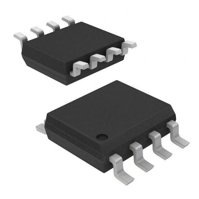
| 产品图片 |
|
| rohs | 符合RoHS无铅 / 符合限制有害物质指令(RoHS)规范要求 |
| 产品系列 | 电阻器网络与阵列,Maxim Integrated MAX5492LC10000+TMAX5492 |
| 数据手册 | |
| 产品型号 | MAX5492LC10000+T |
| 产品 | Divider |
| 产品培训模块 | http://www.digikey.cn/PTM/IndividualPTM.page?site=cn&lang=zhs&ptm=24923http://www.digikey.cn/PTM/IndividualPTM.page?site=cn&lang=zhs&ptm=25703http://www.digikey.cn/PTM/IndividualPTM.page?site=cn&lang=zhs&ptm=25705 |
| 产品目录页面 | |
| 产品种类 | 电阻器网络与阵列 |
| 产品类型 | Networks |
| 供应商器件封装 | SOT-23-5 |
| 其它名称 | MAX5492LC10000+TCT |
| 包装 | 剪切带 (CT) |
| 商标 | Maxim Integrated |
| 外壳宽度 | 1.75 mm |
| 外壳长度 | 3 mm |
| 外壳高度 | 1.45 mm |
| 大小/尺寸 | 0.114" 长 x 0.064" 宽(2.90mm x 1.63mm) |
| 安装类型 | 表面贴装 |
| 容差 | 0.1 % |
| 封装 | Reel |
| 封装/外壳 | SC-74A,SOT-753 |
| 工作温度 | -55°C ~ 125°C |
| 工作温度范围 | - 55 C to + 125 C |
| 工厂包装数量 | 2500 |
| 应用 | - |
| 应用说明 | 点击此处下载产品Datasheet点击此处下载产品Datasheet点击此处下载产品Datasheet点击此处下载产品Datasheet点击此处下载产品Datasheet点击此处下载产品Datasheet点击此处下载产品Datasheet |
| 引脚数 | 5 |
| 标准包装 | 1 |
| 每元件功率 | 160 mW |
| 温度系数 | 35 PPM / C |
| 电压额定值 | 50 V |
| 电路类型 | Divider |
| 电阻(Ω) | 909.1, 9.091k |
| 电阻器数 | 2 |
| 电阻器数量 | 2 |
| 电阻数值 | 10 kOhms |
| 端接类型 | SMD/SMT |
| 管脚数量 | 5 |
| 系列 | MAX5492LC |
| 零件号别名 | MAX5492LC |
| 高度 | 0.057"(1.45mm) |







- 商务部:美国ITC正式对集成电路等产品启动337调查
- 曝三星4nm工艺存在良率问题 高通将骁龙8 Gen1或转产台积电
- 太阳诱电将投资9.5亿元在常州建新厂生产MLCC 预计2023年完工
- 英特尔发布欧洲新工厂建设计划 深化IDM 2.0 战略
- 台积电先进制程称霸业界 有大客户加持明年业绩稳了
- 达到5530亿美元!SIA预计今年全球半导体销售额将创下新高
- 英特尔拟将自动驾驶子公司Mobileye上市 估值或超500亿美元
- 三星加码芯片和SET,合并消费电子和移动部门,撤换高东真等 CEO
- 三星电子宣布重大人事变动 还合并消费电子和移动部门
- 海关总署:前11个月进口集成电路产品价值2.52万亿元 增长14.8%


PDF Datasheet 数据手册内容提取
19-3695; Rev 0; 5/05 Ω 10k Precision-Matched Resistor-Divider in SOT23 General Description Features M The MAX5492 precision resistor-divider consists of two ♦ Resistance Ratios from 1:1 to 10:1 A accurately matched resistors with access to the ends and center of the divider. This device offers excellent ♦ Custom Ratios Available Upon Request X resistance matching of 0.035% (A grade), 0.05% (B ♦ Tight Initial Ratio Accuracy 5 grade), and 0.1% (C grade). The MAX5492 includes an 4 0.035% (MAX5492A) extremely low-resistance-ratio temperature drift of 0.05% (MAX5492B) 9 1.5ppm/°C (typ) over -55°C to +125°C, and has an end- to-end resistance of 10kΩ. Resistance ratios from 1:1 to 0.1% (MAX5492C) 2 10:1 are available. Five standard ratios are available (see ♦ Low 1.5ppm/°C (typ) Resistor-Ratio-Drift (1.1:1) Table 1), and custom ratios are also available upon ♦ Up to 40V Operating Voltage Across Sum of R1 request. To enhance device and system robustness, the and R2 MAX5492 features ±2kV Human Body Model electrostat- ic discharge (ESD) protection to ensure against real- ♦ Tiny 5-Pin SOT23 Package world ESD events. The MAX5492 is ideal for precision gain-setting applications where tight resistance matching and low temperature drift are necessary. The MAX5492 is available in a space-saving 5-pin SOT23 package, and is guaranteed over the military -55°C to +125°C temperature range. Applications Ordering Information* Industrial Process Control RA T IO TE M P PIN - Instrumentation PAR T RA N GE PAC KA G E AC C UR A C Y (% ) Precision Gain Setting MA X5 492_A_ _ _ _ _ - T -5 5° C to + 125°C 5 SO T23-5 0.035 Medical Equipment MA X5 492_B_ _ _ _ _ - T -5 5° C to + 125°C 5 SO T23-5 0.05 Automatic Test Equipment MA X5 492_C_ _ _ _ _ - T -5 5° C to + 125°C 5 SO T23-5 0.1 Base Stations *See the How to Order section for more details. Block Diagram Pin Configuration TOP VIEW MAX5492 P1 SH P1 1 5 SH R1 SL 2 MAX5492 SL P3 P2 3 4 P3 R2 SOT23 P2 ________________________________________________________________Maxim Integrated Products 1 For pricing, delivery, and ordering information,please contact Maxim/Dallas Direct!at 1-888-629-4642, or visit Maxim’s website at www.maxim-ic.com.
Ω 10k Precision-Matched Resistor-Divider in SOT23 2 ABSOLUTE MAXIMUM RATINGS 9 Voltage Between P1 and P2................................................±50V Operating Temperature Range.........................-55°C to +125°C Continuous Current into Any Pin......................................±4.2mA Junction Temperature......................................................+150°C 4 Continuous Power Dissipation (TA = +70°C) Storage Temperature Range.............................-65°C to +150°C 5 5-Pin SOT23 (derate 7.1mW/°C above +70°C).........571.4mW Lead Temperature (soldering, 10s).................................+300°C X 5-Pin SOT23 (θJ-A).....................................................141°C/W A Stresses beyond those listed under “Absolute Maximum Ratings” may cause permanent damage to the device. These are stress ratings only, and functional M operation of the device at these or any other conditions beyond those indicated in the operational sections of the specifications is not implied. Exposure to absolute maximum rating conditions for extended periods may affect device reliability. DC ELECTRICAL CHARACTERISTICS (TA= -55°C to +125°C, unless otherwise noted. Typical values are at TA= +25°C.) (Note 1) PARAMETER SYMBOL CONDITIONS MIN TYP MAX UNITS MAX5492_A, TA = +25°C ±0.035 Initial Resistor-Ratio Error (Note 2) MAX5492_B, TA = +25°C ±0.05 % MAX5492_C, TA = +25°C ±0.1 Ratio 1.1:1 1.5 Resistance-Ratio Temperature Ratio 1.5:1 3 ppm/°C Coefficient (Note 3) Ratio 3.2:1 ≤ ratio ≤ 10:1 5.5 Absolute Temperature Coefficient TCR (Note 4) 35 ppm/°C of Resistance Voltage Coefficient of Resistance VCR (Note 5) 0.1 ppm/V End-to-End Resistance (R1 + R2) 9.25 10 10.75 kΩ Continuous Working Voltage VP1-P2 -40 +40 V Between P1 and P2 P1, P2, P3, SL, SH Capacitance 2 pF Resistance-Ratio Stability 2000 hours at +70°C ±0.03 % -3dB Bandwidth f3dB 1.1:1 ratio (Note 6) 30 MHz Thermal Noise (Note 7) 45 µVRMS Current Noise (Note 8) <-30 dB Maximum Power Rating 160 mW Note 1: The MAX5492 is 100% production tested at TA= +25°C. Specifications over -55°C to +125°C are guaranteed by design and characterization. Note 2: Testing conditions: TA= +25°C, VP1-P2= 10V and 40V. ⎛R ⎞ ∆⎜ 1⎟ ⎝R ⎠ 2 Note 3: Resistance-ratio temperature coefficient is defined R and is guaranteed by design, not production tested. 1 × ∆T R 2 ( ) Note 4: Absolute TCR is defined as ∆ R 1 + R 2 and is tested at 10V and 40V. ( ) R + R × ∆T 1 2 ⎛R ⎞ ∆⎜ 1⎟ Note 5: Resistance-ratio voltage coefficient is defined as ⎝ R ⎠ and is guaranteed by design, not production tested. 2 R 1 × ∆V R 2 2 _______________________________________________________________________________________
Ω 10k Precision-Matched Resistor-Divider in SOT23 DC ELECTRICAL CHARACTERISTICS (continued) M (TA= -55°C to +125°C, unless otherwise noted. Typical values are at TA= +25°C.) (Note 1) A 1 R1 ×R2 X Note 6: Calculate bandwidth by using where C is CP3and R = . 2πRC R1 +R2 5 4 kT Note 7: Calculated according to noise. 9 C 2 Note 8: In accordance with the military specification MIL-STD-202G method 308. Typical Operating Characteristics (VP1-P3= 10V, TA= +25°C, unless otherwise noted.) NORMALIZED RESISTANCE-RATIO DRIFT NORMALIZED RESISTANCE-RATIO DRIFT vs. TEMPERATURE vs. TEMPERATURE 200 600 150 VRPA1T-IPO2 == 11.01V:1 MAX5492 toc01 400 VRAP1T-IPO2 == 31.02V:1 MAX5492 toc02 100 m) m) 200 pp 50 pp T ( T ( F F RI 0 RI 0 D D O O RATI -50 RATI-200 -100 -400 -150 -200 -600 -55 -25 5 35 65 95 125 -55 -25 5 35 65 95 125 TEMPERATURE (°C) TEMPERATURE (°C) NORMALIZED RESISTANCE-RATIO DRIFT RESISTANCE-RATIO ACCURACY vs. TEMPERATURE vs. VOLTAGE 345000000 VRPA1T-IPO2 == 1100:V1 MAX5492 toc03 000...000234 RATIO = 1.1:1 MAX5492 toc04 %) T (ppm) 120000 RACY ( 0.01 RIF CU 0 RATIO D-1000 ATIO AC-0.01 R -0.02 -200 -300 -0.03 -400 -0.04 -55 -25 5 35 65 95 125 0 5 10 15 20 25 30 35 40 TEMPERATURE (°C) VOLTAGE (V) _______________________________________________________________________________________ 3
Ω 10k Precision-Matched Resistor-Divider in SOT23 2 Typical Operating Characteristics (continued) 9 (VP1-P3= 10V, TA= +25°C, unless otherwise noted.) 4 TOTAL HARMONIC DISTORTION 5 FREQUENCY RESPONSE SPECTRAL NOISE DENSITY PLUS NOISE RESPONSE MAX 36 RCAL T=I O1 0=p 1F.1:1 MAX5492 toc05 100 RATIO = 1.1:1 MAX5492 toc06 11000 R20AHTIzO T O= 12.01k:1H z BANDPASS MAX5492 toc07 0 RESPONSE (dB) ---963 √NOISE (nV/Hz) VP1-P2 = 2V VP1-P2 = 10V THD+N (%) 0.11 0.01 -12 0.001 -15 -18 10 0.0001 0.1 1 10 100 1000 10,000100,000 1 10 100 1000 10 100 1k 10k 100k FREQUENCY (kHz) FREQUENCY (Hz) FREQUENCY (Hz) Pin Description PIN NAME FUNCTION 1 P1 R1 Connection Terminal Sense Connection for Low Side of Resistor String. Leave floating or connect in a Kelvin connection 2 SL configuration. 3 P2 R2 Connection Terminal 4 P3 Set-Point Connection Terminal Sense Connection for High Side of Resistor String. Leave floating or connect in a Kelvin connection 5 SH configuration. Detailed Description Applications Information The MAX5492 consists of two precision, low-ratio-drift Kelvin Sensing resistors with an end-to-end resistance of 10kΩ(R1+ R2). Kelvin sensing can improve accuracy in sensitive appli- (See Figure 1.) P3 is the set point of the divider. The cations. Apply a voltage or current at P1 and use sense maximum working voltage of the MAX5492 is 40V. high (SH) and sense low (SL) to monitor the voltage at This device offers a wide range of resistance ratios the upper and lower ends of the resistor string. (R1/R2) from 1:1 to 10:1 and is ideally suited for preci- sion operational-amplifier gain/attenuation control. The MAX5492 features a ±2kV ESD protection that enhances system robustness. A maximum initial ratio accuracy of 0.035% and a low ratio drift enhance sys- tem accuracy. 4 _______________________________________________________________________________________
Ω 10k Precision-Matched Resistor-Divider in SOT23 Typical Applications M A A = VVOIUNT = −RR21 IN A = VVOIUNT = 1 + RR21 X OUT 5 OUT 4 9 P3 2 P3 MAX5492 P2 P1 P2 MAX5492 P1 IN R2 R1 R2 R1 Figure 1. Inverting Amplifier Configuration Figure 2. Noninverting Amplifier Configuration IN A = VVOIUNT = R1 R+2 R2 IN P1 A = VVOIUNT = R1 R+2 R2 MAX5492 P1 R1 MAX5492 P3 R1 P3 OUT OUT R2 R2 P2 P2 Figure 3. Buffered Attenuator Figure 4. Attenuator with Buffer Self-Heating and Error The thermal resistance from junction to ambient, θJ-A, Applying a voltage across terminals P1 and P2 causes for a 5-pin SOT23 package is 141°C/W. Calculate the the device to heat up due to power dissipation. In high- resulting temperature rise as: voltage applications, consider the error in resistance- ∆T = 160mW x 141°C/W = 22.5°C ratio temperature coefficient caused by self-heating. If the ratio temperature coefficient is 1.5ppm/°C (typ), The worst-case self-heating occurs when the operating the total error introduced by self-heating is: voltage attains its maximum value. Approximate the result of power dissipation under this condition as: 22.5°C x 1.5ppm/°C = 33.75ppm ( )2 ( )2 V 40V P = MAX = = 160mW DISS R 10kΩ _______________________________________________________________________________________ 5
Ω 10k Precision-Matched Resistor-Divider in SOT23 2 How to Order 9 4 PREFIX MAX 5492 V A 10000 -T 5 ROOT PART NUMBER X MAX5492 = 10kΩ End-to-End A RATIO RANGE L through W. Resistor ratio must fall in the appropriate M ratio range. (See Table 2.) RATIO ACCURACY A = 0.035% (max); B = 0.05% (max); C = 0.1% (max) RESISTANCE RATIO Five-number ratio designator. Ratios available from 1:1 to 10:1. Format examples: 01000 = 1:1 02500 = 2.5:1 07538 = 7.538:1 10000 = 10:1 TAPE AND REEL Example Part Numbers RESISTOR-RATIO PART NUMBER RESISTOR-RATIO RANGE RESISTOR RATIO ACCURACY (% MAX) MAX5492PA02500-T 2.000 to 2.999 0.035 2.5:1 MAX5492RB03000-T 3.000 to 3.999 0.05 3:1 MAX5492UA07538-T 7.538 to 10.0 0.035 7.538:1 6 _______________________________________________________________________________________
Ω 10k Precision-Matched Resistor-Divider in SOT23 Table 1. Standard Ratios* M A RESISTOR-RATIO RESISTOR-RATIO PART NUMBER RESISTOR RATIO TOP MARK SUFFIX ACCURACY (% MAX) X MAX5492RA01100-T 1.1:1 01100 0.035 AERA 5 MAX5492RB01100-T 1.1:1 01100 0.05 AERC 4 MAX5492RC01100-T 1.1:1 01100 0.1 AERE 9 MAX5492PA01500-T 1.5:1 01500 0.035 AEQU 2 MAX5492PB01500-T 1.5:1 01500 0.05 AEQW MAX5492PC01500-T 1.5:1 01500 0.1 AEQY MAX5492PA03200-T 3.2:1 03200 0.035 AEVE MAX5492PB03200-T 3.2:1 03200 0.05 AEVF MAX5492PC03200-T 3.2:1 03200 0.1 AEVG MAX5492LA07538-T 7.538:1 07538 0.035 AEQB MAX5492LB07538-T 7.538:1 07538 0.05 AEQD MAX5492LC07538-T 7.538:1 07538 0.1 AEQF MAX5492LA10000-T 10:1 10000 0.035 AEQC MAX5492LB10000-T 10:1 10000 0.05 AEQE MAX5492LC10000-T 10:1 10000 0.1 AEQG *Standard ratios are available for ordering in any quantity. Nonstandard ratios are also available for values from 1:1 to 10:1. A minimum order quantity of 10,000 units is required for nonstandard ratios. Contact factory for more information. Table 2. Ratio Ranges Chip Information TRANSISTOR COUNT: 0 LETTER SUFFIX RESISTOR-RATIO RANGE PROCESS: BiCMOS R 1.0 to 1.399 P 1.4 to 1.999 N 2.0 to 2.999 M 3.0 to 7.537 L 7.538 to 10 _______________________________________________________________________________________ 7
Ω 10k Precision-Matched Resistor-Divider in SOT23 2 Package Information 9 (The package drawing(s) in this data sheet may not reflect the most current specifications. For the latest package outline information, 4 go to www.maxim-ic.com/packages.) 5 X S P E A L . 5 3 M T-2 O S PACKAGE OUTLINE, SOT-23, 5L 1 21-0057 E 1 Maxim cannot assume responsibility for use of any circuitry other than circuitry entirely embodied in a Maxim product. No circuit patent licenses are implied. Maxim reserves the right to change the circuitry and specifications without notice at any time. 8 _____________________Maxim Integrated Products, 120 San Gabriel Drive, Sunnyvale, CA 94086 408-737-7600 © 2005 Maxim Integrated Products Printed USA is a registered trademark of Maxim Integrated Products, Inc.
Mouser Electronics Authorized Distributor Click to View Pricing, Inventory, Delivery & Lifecycle Information: M axim Integrated: MAX5492LA07538+T MAX5492LA10000+T MAX5492LB07538+T MAX5492LB10000+T MAX5492LC07538+T MAX5492PA01500+T MAX5492PB01500+T MAX5492PC01500+T MAX5492RA01100+T MAX5492RB01100+T MAX5492RC01100+T MAX5492LC10000+T