ICGOO在线商城 > MAX6709AUB+

 Datasheet下载
- 型号: MAX6709AUB+
- 制造商: Maxim
- 库位|库存: xxxx|xxxx
- 要求:
| 数量阶梯 | 香港交货 | 国内含税 |
| +xxxx | $xxxx | ¥xxxx |
查看当月历史价格
查看今年历史价格
MAX6709AUB+产品简介:
ICGOO电子元器件商城为您提供MAX6709AUB+由Maxim设计生产,在icgoo商城现货销售,并且可以通过原厂、代理商等渠道进行代购。 提供MAX6709AUB+价格参考¥28.01-¥28.01以及MaximMAX6709AUB+封装/规格参数等产品信息。 你可以下载MAX6709AUB+参考资料、Datasheet数据手册功能说明书, 资料中有MAX6709AUB+详细功能的应用电路图电压和使用方法及教程。
MAX6709AUB+是Maxim Integrated推出的一款电源监控器(PMIC - 监控器),主要用于监测系统电源电压,确保电子设备在安全电压范围内稳定运行。该器件广泛应用于对电源可靠性要求较高的嵌入式系统和工业控制领域。

典型应用场景包括:便携式医疗设备、工业自动化控制系统、通信设备、消费类电子产品以及电池供电系统。当系统上电、掉电或电源电压跌落至预设阈值以下时,MAX6709AUB+可产生复位信号,防止微处理器或微控制器因电压不稳而发生误操作或程序跑飞,从而提升系统可靠性。

该型号具有固定复位阈值(约2.93V)、低功耗特性及小型封装(SOT-23-5),适合空间受限且注重能效的应用。其工作温度范围宽(-40°C 至 +125°C),可在恶劣工业环境中稳定运行。此外,内部集成的去抖动电路可避免复位信号抖动,提高抗干扰能力。

综上所述,MAX6709AUB+适用于需要高可靠电源监控的小型化电子系统,尤其适合电池供电和工业级应用环境。
| 参数 | 数值 |
| 产品目录 | 集成电路 (IC)半导体 |
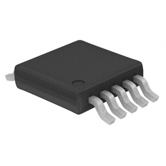
| 描述 | IC VOLT MONITOR QUAD 10-UMAX监控电路 Quad Voltage Monitor |
| 产品分类 | |
| 品牌 | Maxim Integrated |
| 产品手册 | |
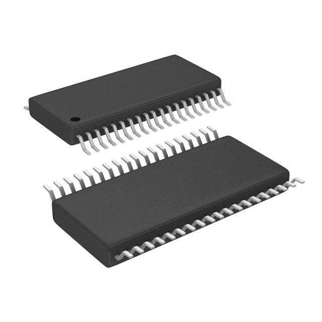
| 产品图片 |
|
| rohs | 符合RoHS无铅 / 符合限制有害物质指令(RoHS)规范要求 |
| 产品系列 | 电源管理 IC,监控电路,Maxim Integrated MAX6709AUB+- |
| NumberofInputsMonitored | 4 Input |
| 数据手册 | |
| 产品型号 | MAX6709AUB+ |
| 产品培训模块 | http://www.digikey.cn/PTM/IndividualPTM.page?site=cn&lang=zhs&ptm=25703http://www.digikey.cn/PTM/IndividualPTM.page?site=cn&lang=zhs&ptm=25705 |
| 产品种类 | 监控电路 |
| 人工复位 | No Manual Reset |
| 供应商器件封装 | 10-uMAX |
| 准确性 | 10 % |
| 包装 | 管件 |
| 受监控电压数 | 4 |
| 商标 | Maxim Integrated |
| 复位 | 低有效 |
| 复位超时 | 最小 <1 ms |
| 安装类型 | 表面贴装 |
| 安装风格 | SMD/SMT |
| 封装 | Tube |
| 封装/外壳 | 10-TFSOP,10-MSOP(0.118",3.00mm 宽) |
| 封装/箱体 | uMAX-10 |
| 工作温度 | -40°C ~ 85°C |
| 工作电源电流 | 80 uA |
| 工厂包装数量 | 50 |
| 应用说明 | |
| 最大工作温度 | + 85 C |
| 最小工作温度 | - 40 C |
| 标准包装 | 1 |
| 欠电压阈值 | 4.25 V, 2.85 V, 2.13 V, Adjustable |
| 电压-阈值 | 2.19V,2.93V,4.38V,可调 |
| 电池备用开关 | No Backup |
| 电源电压-最大 | 5.5 V |
| 电源电压-最小 | 2 V |
| 监视器 | No Watchdog |
| 类型 | Voltage Monitors |
| 系列 | MAX6709 |
| 被监测输入数 | 4 Input |
| 输出 | 开路漏极或开路集电极 |
| 输出类型 | Active Low, Open Drain |
| 过电压阈值 | 4.5 V, 3 V, 2.25 V, Adjustable |
| 重置延迟时间 | 30 us |
| 阈值电压 | 1.8 V, 2.5 V, 3.0 V, 3.3 V, 5 V, Adjustable |
| 零件号别名 | MAX6709 |






- 商务部:美国ITC正式对集成电路等产品启动337调查
- 曝三星4nm工艺存在良率问题 高通将骁龙8 Gen1或转产台积电
- 太阳诱电将投资9.5亿元在常州建新厂生产MLCC 预计2023年完工
- 英特尔发布欧洲新工厂建设计划 深化IDM 2.0 战略
- 台积电先进制程称霸业界 有大客户加持明年业绩稳了
- 达到5530亿美元!SIA预计今年全球半导体销售额将创下新高
- 英特尔拟将自动驾驶子公司Mobileye上市 估值或超500亿美元
- 三星加码芯片和SET,合并消费电子和移动部门,撤换高东真等 CEO
- 三星电子宣布重大人事变动 还合并消费电子和移动部门
- 海关总署:前11个月进口集成电路产品价值2.52万亿元 增长14.8%


PDF Datasheet 数据手册内容提取
19-2379; Rev 1; 12/05 Low-Voltage, High-Accuracy, Quad Voltage Monitors in µMAX Package General Description Features M The MAX6709/MAX6714 quad voltage monitors provide ♦ Monitor Four Power-Supply Voltages A accurate monitoring of up to four supplies without any external components. A variety of factory-trimmed thresh- ♦ Precision Factory-Set Threshold Options for 5.0V, X old voltages and supply tolerances are available to opti- 3.3V, 3.0V, 2.5V, and 1.8V (Nominal) Supplies 6 mize the MAX6709/MAX6714 for specific applications. ♦ Adjustable Voltage Threshold Monitors Down to 7 The selection includes input options for monitoring 5.0V, 0.62V 0 3.3V, 3.0V, 2.5V, and 1.8V voltages. Additional high-input- impedance comparator options can be used as ♦ High-Accuracy (±2.0%) Adjustable Threshold 9 adjustable voltage monitors, general-purpose compara- Inputs /M tors, or digital-level translators. ♦ Low Supply Current A The MAX6709 provides four independent open-drain MAX6709: 35µA outputs with 10µA internal pullup to VCC. The MAX6714 MAX6714: 60µA X provides an active-low, open-drain RESET output with integrated reset timing and three power-fail comparator ♦ Four Independent, Active-Low, Open-Drain 6 7 outputs. Outputs with 10µA Internal Pullup to VCC 1 Each of the monitored voltages is available with trip ♦ 140ms (min) Reset Timeout Period 4 thresholds to support power-supply tolerances of either (MAX6714 only) 5% or 10% below the nominal voltage. An internal ♦ 2.0V to 5.5V Supply Voltage Range bandgap reference ensures accurate trip thresholds across the operating temperature range. ♦ Immune to Supply Transients The MAX6709 consumes only 35µA (typ) of supply cur- ♦ Fully Specified from -40°C to +85°C rent. The MAX6714 consumes only 60µA (typ) of supply current. The MAX6709/MAX6714 operate with supply ♦ Small 10-Pin µMAX Package voltages of 2.0V to 5.5V. An internal undervoltage lock- Ordering Information out circuit forces all four digital outputs low when VCC drops below the minimum operating voltage. The four PART TEMP RANGE PIN-PACKAGE digital outputs have weak internal pullups to VCC, accommodating wire-ORed connections. Each input MAX6709_UB* -40°C to +85°C 10 µMAX threshold voltage has an independent output. The MAX6714_UB* -40°C to +85°C 10 µMAX MAX6709/MAX6714 are available in a 10-pin µMAX *Insert the desired letter from the Selector Guide into the blank package and operate over the extended (-40°C to to complete the part number. +85°C) temperature range. Devices are available in both leaded and lead-free packaging. Specify lead free by adding the + symbol at the end of the part Applications number when ordering. Telecommunications Pin Configurations Servers High-End Printers TOP VIEW Desktop and Notebook Computers Data Storage Equipment IN1 1 10 VCC Networking Equipment IN2 2 9 PWRGD1 MAX6709 Multivoltage Systems IN3 3 8 PWRGD2 IN4 4 7 PWRGD3 GND 5 6 PWRGD4 Typical Operating Circuits appear at end of data sheet. µMAX Selector Guides appear at end of data sheet. Pin Configurations continued at end of data sheet. ________________________________________________________________Maxim Integrated Products 1 For pricing, delivery, and ordering information,please contact Maxim/Dallas Direct!at 1-888-629-4642, or visit Maxim’s website at www.maxim-ic.com.
Low-Voltage, High-Accuracy, Quad Voltage Monitors in µMAX Package 4 ABSOLUTE MAXIMUM RATINGS 1 All Pins to GND.........................................................-0.3V to +6V Operating Temperature Range...........................-40°C to +85°C 7 Input/Output Current (all pins)............................................20mA Storage Temperature Range.............................-65°C to +150°C 6 Continuous Power Dissipation (TA= +70°C) Junction Temperature......................................................+150°C 10-Pin µMAX (derate 5.6mW/°C above +70°C)..........444mW Lead Temperature (soldering, 10s).................................+300°C X Stresses beyond those listed under “Absolute Maximum Ratings” may cause permanent damage to the device. These are stress ratings only, and functional A operation of the device at these or any other conditions beyond those indicated in the operational sections of the specifications is not implied. Exposure to absolute maximum rating conditions for extended periods may affect device reliability. M ELECTRICAL CHARACTERISTICS (MAX6709) / 9 (VCC= 2.0V to 5.5V, TA= -40°C to +85°C, unless otherwise noted. Typical values are at VCC= 5V and TA= +25°C.) (Note 1) 0 PARAMETER SYMBOL CONDITIONS MIN TYP MAX UNITS 7 Supply Voltage Range VCC 2.0 5.5 V 6 VCC = 3V 25 50 X Supply Current ICC µA VCC = 5V 35 65 A VIN_ = input threshold voltage 25 40 M Input Current IIN_ µA VIN_ = 0 to 0.85V (for adjustable threshold) 0.2 5.0V (-5%) 4.50 4.63 4.75 5.0V (-10%) 4.25 4.38 4.50 3.3V (-5%) 3.00 3.08 3.15 3.3V (-10%) 2.85 2.93 3.00 3.0V (-5%) 2.70 2.78 2.85 Threshold Voltage VTH IN_ decreasing V 3.0V (-10%) 2.55 2.63 2.70 2.5V (-5%) 2.25 2.32 2.38 2.5V (-10%) 2.13 2.19 2.25 1.8V (-5%) 1.62 1.67 1.71 1.8V (-10%) 1.53 1.58 1.62 Adjustable Threshold VTH IN_ decreasing 0.609 0.623 0.635 V Threshold Voltage Temperature TCVTH 60 ppm/°C Coefficient Threshold Hysteresis VHYST 0.3 x VTH % VIN_ falling at 10mV/µs from 30 VTH to (VTH - 50mV) Propagation Delay tPD µs VIN_ rising at 10mV/µs from 5 VTH to (VTH + 50mV) VCC = 5V, ISINK = 2mA 0.3 Output Low Voltage VOL VCC = 2.5V, ISINK = 1.2mA 0.3 V VCC = 1V, ISINK = 50µA (Note 2) 0.3 VCC ≥ 2.0V, ISOURCE = 6µA (min), PWRGD_ Output High Voltage VOH unasserted 0.8 x VCC V Output High Source Current IOH VCC ≥ 2.0V, PWRGD_ unasserted 10 µA 2 _______________________________________________________________________________________
Low-Voltage, High-Accuracy Quad, Voltage Monitors in µMAX Package ELECTRICAL CHARACTERISTICS (MAX6714) M (VCC= 2.0V to 5.5V, TA= -40°C to +85°C, unless otherwise noted. Typical values are at VCC= 5V and TA= +25°C.) (Note 1) A PARAMETER SYMBOL CONDITIONS MIN TYP MAX UNITS X Supply Voltage Range VCC 2.0 5.5 V 6 VCC = 3V 60 90 7 Supply Current (Note 3) ICC µA VCC = 5V 80 105 0 Power-Fail Input Current IPFI_ VPFI_ = 0 to 0.85V 0.2 µA 9 MAX6714B (-5%) 4.50 4.63 4.75 / M MAX6714A (-10%) 4.25 4.38 4.50 VCC Reset Threshold VTH VCC decreasing V A MAX6714D (-5%) 3.00 3.08 3.15 MAX6714C (-10%) 2.85 2.93 3.00 X Power-Fail Input Threshold VPFI VPFI_ decreasing 0.609 0.623 0.635 V 6 Threshold Hysteresis VHYST VPFI_ increasing relative to VPFI_ decreasing 0.3 x VTH % 7 Reset Timeout Period tRP 140 210 280 ms 1 VCC falling at 10mV/µs from 4 Reset Delay tRD 30 µs (VTH + 100mV) to (VTH - 100mV) VPFI_ falling at 10mV/µs from VTH to 30 (VTH - 50mV) Power-Fail Propagation Delay tPFD µs VCC falling at 10mV/µs from 5 (VTH + 100mV) to (VTH - 100mV) VIL 0.3 x VCC MR Input Voltage V VIH 0.7 x VCC MR Minimum Input Pulse 1 µs MR Glitch Rejection 100 ns MR to RESET Delay tMRD 200 ns MR Pullup Resistance MR to VCC 10 20 50 kΩ VCC = 5V, ISINK = 2mA 0.3 Output Low Voltage VOL VCC = 2.5V, ISINK = 1.2mA 0.3 V VCC = 1V, ISINK = 50µA (Note 2) 0.3 VCC ≥ 2.0V, ISOURCE = 6mA (min), RESET, Output High Voltage VOH 0.8 x VCC V PFO_ unasserted Output High Source Current IOH VCC ≥ 2.0V, RESET and PFO_ unasserted 10 µA Note 1: 100% production tested at TA= +25°C. Overtemperature limits guaranteed by design. Note 2: Condition at VCC= 1V is guaranteed only from TA= 0°C to +70°C. Note 3: Monitored voltage 5V/3.3V is also the device supply. In the typical condition, supply current splits as follows: 25µA for the resistor-divider, and the rest for other circuitry. _______________________________________________________________________________________ 3
Low-Voltage, High-Accuracy, Quad Voltage Monitors in µMAX Package 4 Typical Operating Characteristics 1 (VCC= 5V, TA = +25°C, unless otherwise noted.) 7 6 SUPPLY CURRENT SUPPLY CURRENT NORMALIZED THRESHOLD ERROR X vs. SUPPLY VOLTAGE (MAX6709) vs. SUPPLY VOLTAGE (MAX6714) vs. SUPPLY VOLTAGE (MAX6709) X6709/MA µSUPPLY CURRENT (A) 1223344550505050 TA = +25T°AC = +85°C TA = -40°C MAX6709/14 toc01 µSUPPLY CURRENT (A) 13456789000000000 TA = +25°C TA = +8T5A° =C -40°C MAX6709/14 toc02 ALIZED THRESHOLD ERROR (%) 00000000........0000000012345678 NORMALIZED TO VCC = 5V MAX6709/14 toc03 M 10 20 R 0 O A N 5 10 -0.01 M 0 0 -0.02 0 0.5 1.0 1.5 2.0 2.5 3.0 3.5 4.0 4.5 5.0 5.5 0 0.5 1.0 1.5 2.0 2.5 3.0 3.5 4.0 4.5 5.0 5.5 2.0 2.5 3.0 3.5 4.0 4.5 5.0 5.5 SUPPLY VOLTAGE (V) SUPPLY VOLTAGE (V) SUPPLY VOLTAGE (V) NORMALIZED THRESHOLD NORMALIZED PFI_ THRESHOLD OUTPUT VOLTAGE LOW vs. TEMPERATURE (MAX6709) vs. TEMPERATURE (MAX6714) vs. SINK CURRENT 0.20 1.010 200 NORMALIZED THRESHOLD --00000.....01110005505 MAX6709/14 toc04 ORMALIZED PFI_ THRESHOLD 0011111.......990000099000006802468 VCC = 3V OR 5V MAX6709/14 toc05 OUTPUT VOLTAGE LOW (mV) 1111168024680000000 TA = +25°TCA = +85°C TA = -40°C MAX6709/14 toc06 N 0.994 40 -0.15 0.992 20 -0.20 0.990 0 -40 -15 10 35 60 85 -40 -15 10 35 60 85 0 1 2 3 4 5 6 7 8 9 10 TEMPERATURE (°C) TEMPERATURE (°C) SINK CURRENT (mA) MAXIMUM TRANSIENT DURATION MAXIMUM TRANSIENT DURATION RESET TIMEOUT PERIOD vs. VCC OVERDRIVE (MAX6714) vs. PFI_ OVERDRIVE (MAX6714) vs. TEMPERATURE (MAX6714) µMAXIMUM TRANSIENT DURATION (s) 1112345678901200000000000 ARBEOSVEET TAHSISSE LRITNSE MAX6709/14 toc07 µMAXIMUM TRANSIENT DURATION (s) 1112345678901200000000000 PAFBOO_V EA STHSEISR TLSINE MAX6709/14 toc08 RESET TIMEOUT PERIOD (ms) 222222111111123456 MAX6709/14 toc09 10 10 0 0 210 0 100 200 300 400 500 600 700 800 9001000 0 20 40 100 500 1000 -40 -15 10 35 60 85 VCC OVERDRIVE (mV) PFI_ OVERDRIVE (mV) TEMPERATURE (°C) 4 _______________________________________________________________________________________
Low-Voltage, High-Accuracy Quad, Voltage Monitors in µMAX Package Typical Operating Characteristics (continued) M (VCC= 5V, TA= +25°C, unless otherwise noted.) A X PROPAGATION DELAY PFO_ PULLUP AND PULLDOWN RESPONSE 6 (WITH 100mV OVERDRIVE) (CPFO_ = 47pF) 7 MAX6709/14 toc10 MAX6709/14 toc11 0 9 IN_ (PFI_) PFI_ / 100mV/div 50mV/div M AC-COUPLED AC-COUPLED A X 6 PWRGD_ (PFO_) PFO_ 2V/div 2V/div 7 1 4 10µs/div 10µs/div RESET TIMEOUT DELAY MAX6709/14 toc12 MR 2V/div RESET 2V/div 40ms/div _______________________________________________________________________________________ 5
Low-Voltage, High-Accuracy, Quad Voltage Monitors in µMAX Package 4 Pin Description 1 PIN 7 NAME FUNCTION 6 MAX6709 MAX6714 X 1 — IN1 Input Voltage 1. See Selector Guide for monitored voltages. 2 — IN2 Input Voltage 2. See Selector Guide for monitored voltages. A 3 — IN3 Input Voltage 3. See Selector Guide for monitored voltages. M 4 — IN4 Input Voltage 4. See Selector Guide for monitored voltages. / 9 5 5 GND Ground 0 Output 4. PWRGD4 asserts low when IN4 falls below its threshold voltage. PWRGD4 is open 6 — PWRGD4 7 drain with a 10µA internal pullup current source to VCC. 6 Output 3. PWRGD3 asserts low when IN3 falls below its threshold voltage. PWRGD3 is open 7 — PWRGD3 X drain with a 10µA internal pullup current source to VCC. A Output 2. PWRGD2 asserts low when IN2 falls below its threshold voltage. PWRGD2 is open 8 — PWRGD2 M drain with a 10µA internal pullup current source to VCC. Output 1. PWRGD1 asserts low when IN1 falls below its threshold voltage. PWRGD1 is open 9 — PWRGD1 drain with a 10µA internal pullup current source to VCC. Power-Supply Input. Connect VCC to a 2.0V to 5.5V supply. An undervoltage lockout circuit forces all PWRGD_ outputs low when VCC drops below the minimum operating voltage. VCC 10 10 VCC is not a monitored voltage for the MAX6709. For the MAX6714, RESET asserts low when VCC drops below its threshold. Manual Reset Input. Force MR low to assert the RESET output. RESET remains asserted for — 1 MR the reset timeout period after MR goes high. MR is internally pulled up to VCC. Power-Fail Input 1. Input to noninverting input of the power-fail comparator. PFI1 is — 2 PFI1 compared to an internal 0.62V reference. Use an external resistor-divider network to adjust the monitor threshold. Power-Fail Input 2. Input to noninverting input of the power-fail comparator. PFI2 is — 3 PFI2 compared to an internal 0.62V reference. Use an external resistor-divider network to adjust the monitor threshold. Power-Fail Input 3. Input to noninverting input of the power-fail comparator. PFI3 is — 4 PFI3 compared to an internal 0.62V reference. Use an external resistor-divider network to adjust the monitor threshold. Power-Fail Output 3. PFO3 is an active-low, open-drain output with a 10µA internal pullup to — 6 PFO3 VCC. PFO3 asserts low when PFI3 is below the selected threshold. Power-Fail Output 2. PFO2 is an active-low, open-drain output with a 10µA internal pullup to — 7 PFO2 VCC. PFO2 asserts low when PFI2 is below the selected threshold. Power-Fail Output 1. PFO1 is an active-low, open-drain output with a 10µA internal pullup to — 8 PFO1 VCC. PFO1 asserts low when PFI1 is below the selected threshold. Reset Output. RESET is an active-low, open-drain output that asserts low when VCC drops — 9 RESET below its preset threshold voltage or when a manual reset is initiated. RESET remains low for the reset timeout period after VCC exceeds the selected reset threshold or MR is released. 6 _______________________________________________________________________________________
Low-Voltage, High-Accuracy Quad, Voltage Monitors in µMAX Package Detailed Description flow from the external pullup voltage to VCC. The out- M puts can be wire-ORed for a single power-good signal. The MAX6709/MAX6714 are low-power, quad voltage A monitors designed for multivoltage systems. Preset The MAX6709 quad voltage monitor includes an accu- voltage options for 5.0V, 3.3V, 3.0V, 2.5V, and 1.8V rate reference, four precision comparators, and a X make these quad monitors ideal for applications such series of internally trimmed resistor-divider networks to 6 as telecommunications, desktop and notebook comput- set the factory-fixed threshold options. The resistor net- 7 ers, high-end printers, data storage equipment, and works scale the specified IN_ reset voltages to match 0 networking equipment. the internal reference/comparator voltage. Adjustable threshold options bypass the internal resistor networks 9 The MAX6709/MAX6714 have an internally trimmed and connect directly to one of the comparator inputs / threshold that minimizes or eliminates the need for M (an external resistor-divider network is required for external components. The four open-drain outputs have threshold matching). The MAX6709 monitors power A weak (10µA) internal pullups to VCC, allowing them to supplies with either 5% or 10% tolerance specifica- interface easily with other logic devices. The weak inter- X tions, depending on the selected version. Additional nal pullups can be overdriven by external pullups to any high-input-impedance comparator options can be used 6 voltage from 0 to 5.5V. Internal circuitry prevents current 7 1 VCC 4 IN1 (ADJ) PWRGD1 VCC IN2 (3.3V/3.0V) PWRGD2 VCC IN3 (2.5V/1.8V) PWRGD3 VCC IN4 (ADJ) PWRGD4 VCC 0.62V REFERENCE UNDERVOLTAGE LOCKOUT MAX6709 Figure 1. MAX6709 Functional Diagram _______________________________________________________________________________________ 7
Low-Voltage, High-Accuracy, Quad Voltage Monitors in µMAX Package 4 1 VCC 7 MR 6 X RESET TIMEOUT A (200ms) VCC M (5.0V/3.3V) / 9 VCC 0 7 PFI1 6 (ADJ) PFO1 X A M VCC PFI2 (ADJ) PFO2 VCC PFI3 (ADJ) PFO3 VCC 0.62V REFERENCE UNDERVOLTAGE LOCKOUT MAX6714 Figure 2. MAX6714 Functional Diagram as an adjustable voltage monitor, general-purpose Applications Information comparator, or digital-level translator. Hysteresis The MAX6714 quad voltage monitor/reset offers one When the voltage on one comparator input is at or near fixed input with internal timing for µP reset, three power- the voltage on another input, ambient noise generally fail comparators, and a manual reset input (MR). RESET causes the comparator output to oscillate. The most asserts low when VCCdrops below its threshold or MRis common way to eliminate this problem is through hys- driven low. Each of the three power-fail inputs connects teresis. When the two comparator input voltages are directly to one of the comparator inputs. equal, hysteresis causes one comparator input voltage When any input is higher than the threshold level, the to move quickly past the other, thus taking the input out output is high. The output goes low as the input drops of the region where oscillation occurs. Standard com- below the threshold voltage. The undervoltage lockout parators require hysteresis to be added through the circuitry remains active and all outputs remain low with use of external resistors. The external resistive network VCCdown to 1V (Figures 1 and 2). usually provides a positive feedback to the input in order to cause a jump in the threshold voltage when output toggles in one direction or the other. These 8 _______________________________________________________________________________________
Low-Voltage, High-Accuracy Quad, Voltage Monitors in µMAX Package M 5V 5V A VCC V1 IN1 X V2 IN2 6 MAX6709 VCC D1 V3 IN3 VIN (5V) IN1 PWRGD1 7 V4 IN4 MAX6709 D2 0 IN2 PWRGD2 9 PWRGD1 PWRGD2 D3 /M IN3 PWRGD3 PWRGD3 A D4 PWRGD4 IN4 PWRGD4 X GND GND 6 7 Figure 3. Quad Undervoltage Detector with LED Indicators Figure 4. VCCBar Graph Monitoring 1 4 VTH1 = (1 + RR 21 ) VREF 5V PWRGD1 VREF = 0.62V R2 VCC VTH1 IN1 PWRGD1 R1 MAX6709 IN2 PWRGD2 OUT INPUT PWRGD4 IN3 PWRGD3 VTH4 R4 IN4 PWRGD4 GND R3 VTH4 = (1 + RR 43 ) VREF OUT ∆VTH Figure 5. Window Detection Figure 6. Output Response of Window Detector Circuit resistors are not required when using the MAX6709/ Window Detection MAX6714 because hysteresis is built into the device. A window detector circuit uses two auxiliary inputs in a MAX6709/MAX6714 hysteresis is typically 0.3% of the configuration such as the one shown in Figure 5. threshold voltage. External resistors R1–R4 set the two threshold voltages (VTH1and VTH4) of the window detector circuit. Window Undervoltage Detection Circuit width (∆VTH) is the difference between the threshold The open-drain outputs of the MAX6709/MAX6714 can voltages (Figure 6). be configured to detect an undervoltage condition. Figure 3 shows a configuration where an LED turns on Adjustable Input when the comparator output is low, indicating an The MAX6709 offers several monitor options with undervoltage condition. adjustable reset thresholds. The MAX6714 has three monitored inputs with adjustable thresholds. The thresh- The MAX6709/MAX6714 can also be used in applica- old voltage at each adjustable IN_ (PFI_) input is typically tions such as system supervisory monitoring, multivolt- 0.62V. To monitor a voltage >0.62V, connect a resistor- age level detection, and VCC bar graph monitoring divider network to the circuit as shown in Figure 7. (Figure 4). VINTH= 0.62V ✕(R1 + R2) / R2 _______________________________________________________________________________________ 9
Low-Voltage, High-Accuracy, Quad Voltage Monitors in µMAX Package 4 Or, solved in terms of R1: noisy environment, connecting a 0.1µF capacitor from MRto GND provides additional noise immunity. 1 R1 = R2 ((VINTH/ 0.62V) - 1) 7 Reseting the µP from a 2nd Voltage 6 (MAX6714) X The MAX6714 can be configured to assert a reset from a VINTH second voltage by connecting the power-fail output to A manual reset. As the VPFI_ falls below its threshold, PFO M R1 goes low and asserts the reset output for the reset time- out period after the manual reset input is deasserted. / 9 (See Typical Operating Circuit.) 0 R2 Power-Supply Bypassing and Grounding 7 The MAX6709/MAX6714 operate from a single 2.0V to 6 5.5V supply. In noisy applications, bypass VCC with a X 0.1µF capacitor as close to VCCas possible. VREF = 0.62V A R1 = R2 ( V I N T H - 1) M 0.62V Figure 7. Setting the Auxiliary Monitor VCC VTH_ VTH_ Unused Inputs The unused inputs (except the adjustable) are internally connected to ground through the lower resistors of the threshold-setting resistor pairs. The adjustable input, however, must be connected to ground if unused. RESET 90% Reset Output 10% The MAX6714 RESET output asserts low when VCC drops below its specified threshold or MR asserts low tRD tRP and remains low for the reset timeout period (140ms min) after VCC exceeds its threshold and MRdeasserts Figure 8. RESETOutput Timing Diagram (Figure 8). The output is open drain with a weak (10µA) internal pullup to VCC. For many applications, no exter- nal pullup resistor is required to interface with other logic devices. An external pullup resistor to any voltage VCC = 3.3V 5V from 0 to 5.5V overdrives the internal pullup if interfac- ing to different logic supply voltages (Figure 9). Internal circuitry prevents reverse current flow from the external 100kΩ pullup voltage to VCC. VCC VCC Manual Reset Input Many µP-based products require manual reset capabili- RESET ty, allowing the operator, a test technician, or external RESET logic circuitry to initiate a reset. A logic low on MR asserts RESETlow. RESETremains asserted while MRis low, and during the reset timeout period (140ms min) after MRreturns high. The MRinput has an internal 20kΩ pullup resistor to VCC, so it can be left open if unused. MAX6714 Drive MR with TTL or CMOS-logic levels, or with open- GND GND drain/collector outputs. Connect a normally open momen- tary switch from MR to GND to create a manual reset function; external debounce circuitry is not required. If MRis driven from long cables or if the device is used in a Figure 9. Interfacing to Different Logic Supply Voltage 10 ______________________________________________________________________________________
Low-Voltage, High-Accuracy Quad, Voltage Monitors in µMAX Package Selector Guide (MAX6709) Selector Guide (MAX6714) M NOMINAL INPUT VOLTAGE NOMINAL INPUT VOLTAGE A SUPPLY SUPPLY X PART IN1 IN2 IN3 IN4 PART VCC PFI1 PFI2 PFI3 TOLERANCE TOLERANCE 6 (V) (V) (V) (V) (V) (V) (V) (V) (%) (%) 7 MAX6709AUB 5 3.3 2.5 Adj* 10 MAX6714AUB 5 Adj* Adj* Adj* 10 0 MAX6709BUB 5 3.3 2.5 Adj* 5 MAX6714BUB 5 Adj* Adj* Adj* 5 9 MAX6709CUB 5 3.3 1.8 Adj* 10 MAX6714CUB 3.3 Adj* Adj* Adj* 10 / M MAX6709DUB 5 3.3 1.8 Adj* 5 MAX6714DUB 3.3 Adj* Adj* Adj* 5 MAX6709EUB Adj* 3.3 2.5 1.8 10 *Adjustable voltage based on 0.62V internal threshold. External A MAX6709FUB Adj* 3.3 2.5 1.8 5 threshold voltage can be set using an external resistor-divider. X MAX6709GUB 5 3.3 Adj* Adj* 10 6 Pin Configurations (continued) MAX6709HUB 5 3.3 Adj* Adj* 5 7 MAX6709IUB Adj* 3.3 2.5 Adj* 10 1 TOP VIEW MAX6709JUB Adj* 3.3 2.5 Adj* 5 4 MAX6709KUB Adj* 3.3 1.8 Adj* 10 MR 1 10 VCC MAX6709LUB Adj* 3.3 1.8 Adj* 5 PFI1 2 9 RESET MAX6709MUB Adj* 3 Adj* Adj* 10 MAX6714 PFI2 3 8 PFO1 MAX6709NUB Adj* 3 Adj* Adj* 5 PFI3 4 7 PFO2 MAX6709OUB Adj* Adj* Adj* Adj* N/A GND 5 6 PFO3 *Adjustable voltage based on 0.62V internal threshold. External threshold voltage can be set using an external resistor-divider. µMAX Chip Information TRANSISTOR COUNT: 1029 PROCESS: BiCMOS ______________________________________________________________________________________ 11
Low-Voltage, High-Accuracy, Quad Voltage Monitors in µMAX Package 4 Typical Operating Circuit (MAX6709) 1 7 2.0V TO 5.5V 6 (MAY BE ONE OF THE MONITORED VOLTAGES) X VCC A IN1 PWRGD1 M / SUPPLIES IN2 MAX6709 PWRGD2 9 TO BE SYSTEM µP MONITORED LOGIC 0 IN3 PWRGD3 7 6 IN4 PWRGD4 X GND A M Typical Operating Circuit (MAX6714) 3.3V SUPPLY 5V SUPPLY VCC VCC RESET RESET 9V SUPPLY PFI1 MR MAX6714 PFI2 PFO1 µP PFI3 PFO2 I/O VBATT PFO3 I/O GND 12 ______________________________________________________________________________________
Low-Voltage, High-Accuracy, Quad Voltage Monitors in µMAX Package Package Information M (The package drawing(s) in this data sheet may not reflect the most current specifications. For the latest package outline information, A go to www.maxim-ic.com/packages.) X S P 6 E e 4X S X. 7 A 10 10 INCHES MILLIMETERS UM 0 DIM MIN MAX MIN MAX 10L 9 A - 0.043 - 1.10 A1 0.002 0.006 0.05 0.15 / M A2 0.030 0.037 0.75 0.95 D1 0.116 0.120 2.95 3.05 A D2 0.114 0.118 2.89 3.00 H E1 0.116 0.120 2.95 3.05 X Ø0.50±0.1 E2 0.114 0.118 2.89 3.00 6 H 0.187 0.199 4.75 5.05 0.6±0.1 L 0.0157 0.0275 0.40 0.70 7 L1 0.037 REF 0.940 REF 1 b 0.007 0.0106 0.177 0.270 4 1 1 e 0.0197 BSC 0.500 BSC 0.6±0.1 c 0.0035 0.0078 0.090 0.200 BOTTOM VIEW TOP VIEW S 0.0196 REF 0.498 REF α 0° 6° 0° 6° D2 E2 GAGE PLANE A2 A c b α E1 L A1 D1 L1 FRONT VIEW SIDE VIEW PROPRIETARY INFORMATION TITLE: PACKAGE OUTLINE, 10L uMAX/uSOP APPROVAL DOCUMENT CONTROL NO. REV. 1 21-0061 1 Maxim cannot assume responsibility for use of any circuitry other than circuitry entirely embodied in a Maxim product. No circuit patent licenses are implied. Maxim reserves the right to change the circuitry and specifications without notice at any time. Maxim Integrated Products, 120 San Gabriel Drive, Sunnyvale, CA 94086 408-737-7600 ____________________13 © 2005 Maxim Integrated Products Printed USA is a registered trademark of Maxim Integrated Products, Inc.