ICGOO在线商城 > MAX9503GETE+T

 Datasheet下载
- 型号: MAX9503GETE+T
- 制造商: Maxim
- 库位|库存: xxxx|xxxx
- 要求:
| 数量阶梯 | 香港交货 | 国内含税 |
| +xxxx | $xxxx | ¥xxxx |
查看当月历史价格
查看今年历史价格
MAX9503GETE+T产品简介:
ICGOO电子元器件商城为您提供MAX9503GETE+T由Maxim设计生产,在icgoo商城现货销售,并且可以通过原厂、代理商等渠道进行代购。 提供MAX9503GETE+T价格参考¥5.08-¥13.57以及MaximMAX9503GETE+T封装/规格参数等产品信息。 你可以下载MAX9503GETE+T参考资料、Datasheet数据手册功能说明书, 资料中有MAX9503GETE+T详细功能的应用电路图电压和使用方法及教程。
MAX9503GETE+T是Maxim Integrated推出的一款高性能视频放大器,属于线性器件中的视频放大器模块。该器件主要面向需要高质量模拟视频信号处理的应用场景。其典型应用包括便携式视频设备、安防监控系统、车载摄像头系统以及工业视频传输设备等。

该芯片支持单通道或双通道视频信号驱动,具备宽频带和高输出驱动能力,可支持NTSC、PAL等多种标准模拟视频格式,适用于驱动75Ω负载的复合视频(CVBS)或S-Video信号输出。其低功耗特性使其非常适合电池供电设备,如手持式监控仪、移动医疗成像设备和无人机视频传输模块。

MAX9503GETE+T采用小型化TQFN封装,节省PCB空间,适合高密度布局设计。同时,它集成内部偏置电路和直流恢复功能,简化了外部设计,提高了系统稳定性与可靠性。在需要清晰、稳定视频显示的中高端工业和消费类电子产品中具有广泛应用前景。
| 参数 | 数值 |
| -3db带宽 | - |
| 产品目录 | 集成电路 (IC) |
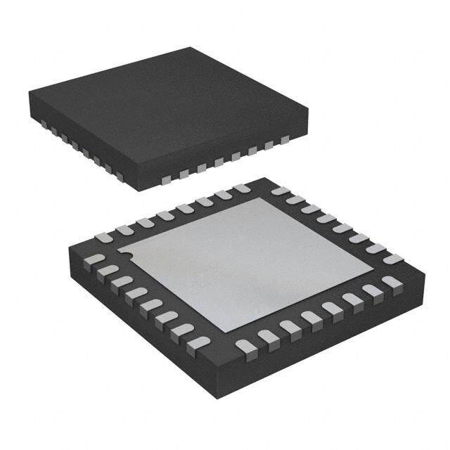
| 描述 | IC VIDEO AMP W/FILTER 16-TQFN |
| 产品分类 | |
| 品牌 | Maxim Integrated |
| 数据手册 | |
| 产品图片 |
|
| 产品型号 | MAX9503GETE+T |
| rohs | 无铅 / 符合限制有害物质指令(RoHS)规范要求 |
| 产品系列 | DirectDrive® |
| 产品培训模块 | http://www.digikey.cn/PTM/IndividualPTM.page?site=cn&lang=zhs&ptm=25703http://www.digikey.cn/PTM/IndividualPTM.page?site=cn&lang=zhs&ptm=25705 |
| 产品目录页面 | |
| 供应商器件封装 | 16-TQFN-EP(3x3) |
| 其它名称 | MAX9503GETE+TCT |
| 包装 | 剪切带 (CT) |
| 压摆率 | - |
| 安装类型 | 表面贴装 |
| 封装/外壳 | 16-WFQFN 裸露焊盘 |
| 应用 | |
| 标准包装 | 1 |
| 电压-电源,单/双 (±) | 2.7 V ~ 3.6 V |
| 电流-电源 | 12mA |
| 电流-输出/通道 | 50mA |
| 电路数 | 1 |
| 输出类型 | - |








- 商务部:美国ITC正式对集成电路等产品启动337调查
- 曝三星4nm工艺存在良率问题 高通将骁龙8 Gen1或转产台积电
- 太阳诱电将投资9.5亿元在常州建新厂生产MLCC 预计2023年完工
- 英特尔发布欧洲新工厂建设计划 深化IDM 2.0 战略
- 台积电先进制程称霸业界 有大客户加持明年业绩稳了
- 达到5530亿美元!SIA预计今年全球半导体销售额将创下新高
- 英特尔拟将自动驾驶子公司Mobileye上市 估值或超500亿美元
- 三星加码芯片和SET,合并消费电子和移动部门,撤换高东真等 CEO
- 三星电子宣布重大人事变动 还合并消费电子和移动部门
- 海关总署:前11个月进口集成电路产品价值2.52万亿元 增长14.8%




PDF Datasheet 数据手册内容提取
19-3676; Rev 1; 8/05 EVAALVUAAILTAIOBNL EKIT DirectDrive Video Amplifier with Reconstruction Filter General Description Features M The MAX9503 filters and amplifies standard-definition ♦ DC-Coupled Output A video signals. Maxim’s DirectDrive™ technology elimi- nates large output-coupling capacitors and sets the ♦ Direct Connection to Video DAC X video black level to ground. The input of the MAX9503 ♦ Video Output Black Level Set to Ground 9 can be directly connected to the output of a video 5 digital-to-analog converter (DAC). The MAX9503 pro- ♦ Video Reconstruction Filter with 50dB 0 vides a compact, integrated, and low-power solution. Attenuation at 27MHz 3 An internal reconstruction filter smoothes the steps and ♦ Preset Gain reduces the spikes on the video signal from the DAC. 6dB (MAX9503G) The reconstruction filter typically has 3dB attenuation at 12dB (MAX9503M) 9MHz and 50dB attenuation at 27MHz, and ±1dB pass- ♦ 10nA Shutdown Supply Current band flatness to 5.5MHz. Maxim’s DirectDrive uses an integrated charge pump ♦ 2.7V to 3.6V Single-Supply Operation and a linear regulator to create a clean negative power supply to drive the sync below ground. The charge pump injects so little noise into the video output that the picture is visibly flawless. Ordering Information The MAX9503 is available with +6dB (MAX9503G) and PIN- +12dB (MAX9503M) gains. The device operates from a PART* PKG CODE TOP MARK PACKAGE 2.7V to 3.6V single supply and features a 10nA low- power shutdown mode. MAX9503GEEE 16 QSOP E16-4 — The MAX9503 is offered in space-saving 16-pin QSOP MAX9503GETE 16 TQFN T1633-4 ACU and 16-pin TQFN packages and is specified over the MAX9503MEEE 16 QSOP E16-4 — -40°C to +85°C extended temperature range. MAX9503METE 16 TQFN T1633-4 ACV Applications *All devices are specified over the -40°C to +85°C operating temperature range. Digital Still Cameras Mobile Phones/Smartphones Functional Diagram/Typical Operating Circuit and Pin Security Cameras Configurations appear at end of data sheet. Portable Media Players Space-Constrained, Low-Power Portable Devices Block Diagram -0.1V TO 0 TO 50mV MAX9503 +0.1V 0V BUFFER 0V VIDIN LOWPASS VIDOUT AMP FILTER LINEAR REGULATOR MAX9503G: 6dB CHARGE MAX9503M: 12dB PUMP ________________________________________________________________Maxim Integrated Products 1 For pricing, delivery, and ordering information,please contact Maxim/Dallas Direct!at 1-888-629-4642, or visit Maxim’s website at www.maxim-ic.com.
DirectDrive Video Amplifier with Reconstruction Filter 3 ABSOLUTE MAXIMUM RATINGS 0 VDDto SGND............................................................-0.3V to +4V VIDOUT Short Circuit to VDD, SGND 5 VIDIN to SGND.........................................................-0.3V to +4V and the Greater of (VSSand -2V)...........................Continuous 9 BIAS to SGND............................................-0.3V to (VDD+ 0.3V) Continuous Current SHDNto SGND........................................................-0.3V to +4V VIDIN, BIAS, SHDN......................................................±20mA X VIDOUT to SGND........................(The greater of VSSand -2V) to Continuous Power Dissipation (TA= +70°C) A (VDD+ 0.3V) 16-Pin QSOP (derate 8.3mW/°C above +70°C)...........667mW CPVDDto CPGND....................................................-0.3V to +4V 16-Pin TQFN (derate 15.6mW/°C above +70°C).......1349mW M C1P, C1N, CPVSS.............................Capacitor Connection Only Operating Temperature Range...........................-40°C to +85°C CPGND, SGND, GND............................................-0.1V to +0.1V Junction Temperature......................................................+150°C CPVSSto VSS..................................................................-0.1V to +0.1V Storage Temperature Range.............................-65°C to +150°C Lead Temperature (soldering, 10s).................................+300°C Stresses beyond those listed under “Absolute Maximum Ratings” may cause permanent damage to the device. These are stress ratings only, and functional operation of the device at these or any other conditions beyond those indicated in the operational sections of the specifications is not implied. Exposure to absolute maximum rating conditions for extended periods may affect device reliability. ELECTRICAL CHARACTERISTICS (VDD = CPVDD = SHDN = 3.0V, SGND = GND = CPGND = 0V, C1 = C2 = C3 = C4 = 1µF, RBIAS = 100kΩ, TA = TMIN to TMAX. RL = 150Ω to SGND, unless otherwise noted. VVIDIN = 286mV (MAX9503G), VVIDIN = 143mV (MAX9503M). Typical values are at VDD= CPVDD = SHDN= 3.0V, TA= +25°C, unless otherwise noted.) (Note 1) PARAMETER SYMBOL CONDITIONS MIN TYP MAX UNITS VDD, Guaranteed by DC voltage gain and Supply Voltage Range 2.7 3.6 V CPVDD quiescent current Quiescent Supply Current IDD VDD = 3.6V (IDD = IVDD + ICPVDD, RL = ∞) 12 15 mA VDD = 3.6V (ISHDN = IVDD + ICPVDD), Shutdown Supply Current ISHDN 0.01 1 µA SHDN = SGND Bias Voltage VBIAS 1 V VIDEO AMPLIFIER Guaranteed by DC MAX9503G -0.10 +1.05 voltage gain, VDD = 2.7V MAX9503M -0.050 +0.525 Input Voltage Range VRANGE V Guaranteed by DC MAX9503G -0.10 +1.28 voltage gain, VDD = 3V MAX9503M -0.05 +0.64 Input Current IIN VDD = 2.7V -2.5 +2.5 µA Input Resistance RIN 1 MΩ MAX9503G 5.5 6 6.5 DC Voltage Gain (Note 2) AV VDD = 2.7V to 3.6V dB MAX9503M 11.5 12 12.5 MAX9503G -0.1 0 +0.1 Output Black Level (Note 3) VDD = 2.7V V MAX9503M -0.15 0 +0.15 Guaranteed by DC voltage gain, VDD = 2.7V 2.162 Output Voltage Swing VP-P Guaranteed by DC voltage gain, VDD = 3V 2.594 Output Short-Circuit Current ISC Sinking or sourcing 50 mA MAX9503G 0.01 Output Resistance ROUT Ω MAX9503M 0.02 MAX9503G 4.2 Shutdown Output Impedance ROUTSHDN SHDN = SGND kΩ MAX9503M 8.2 2 _______________________________________________________________________________________
DirectDrive Video Amplifier with Reconstruction Filter ELECTRICAL CHARACTERISTICS (continued) M (VDD = CPVDD = SHDN = 3.0V, SGND = GND = CPGND = 0V, C1 = C2 = C3 = C4 = 1µF, RBIAS = 100kΩ, TA = TMIN to TMAX. A RL = 150Ω to SGND, unless otherwise noted. VVIDIN = 286mV (MAX9503G), VVIDIN = 143mV (MAX9503M). Typical values are at VDD= CPVDD = SHDN= 3.0V, TA= +25°C, unless otherwise noted.) (Note 1) X 9 PARAMETER SYMBOL CONDITIONS MIN TYP MAX UNITS 5 CHARGE PUMP 0 Switching Frequency 150 250 300 kHz 3 LOGIC SIGNALS Logic-Low Threshold VIL VDD = 2.7V to 3.6V 0.5 V Logic-High Threshold VIH VDD = 2.7V to 3.6V 1.5 V Logic Input Current IIL 1 µA AC ELECTRICAL CHARACTERISTICS (VDD = CPVDD = SHDN= 3.0V, SGND = GND = CPGND = 0V, C1 = C2 = C3 = C4 = 1µF, RBIAS= 100kΩ, TA= TMINto TMAX. RL = 150Ω to SGND, unless otherwise noted. VVIDIN = 286mV (MAX9503G), VVIDIN = 143mV (MAX9503M). Typical values are at VDD = CPVDD = SHDN= 3.0V, TA= +25°C, unless otherwise noted.) (Note 1) PARAMETER SYMBOL CONDITIONS MIN TYP MAX UNITS Passband Flatness VDD = 2.7V, f = 100kHz to 5.5MHz -1 0 +1 dB VDD = 2.7V, f = 9.1MHz 3 Attenuation VIDOUT= 2VP-P, attenuation dB is referred to 100kHz f = 27MHz 35 50 MAX9503G 62 Power-Supply Rejection Ratio PSRR f = 100kHz dB MAX9503M 56 MAX9503G 0.5 Output Impedance ZOUT f = 5MHz Ω MAX9503M 0.65 MAX9503G 0.1 Differential Gain Error DG NTSC, VIDOUT = 2VP-P % MAX9503M 0.1 MAX9503G 0.2 Differential Phase Error DP NTSC, VIDOUT = 2VP-P De gre es MAX9503M 0.2 2T = 250ns, bar time is 18µs, the beginning 2T Pulse-to-Bar K Rating 2.5% and the ending 2.5% of the bar time -0.3 K% are ignored 2T Pulse Response 2T = 250ns 0.3 K% 2T = 250ns, bar time is 18µs, the beginning 2T Bar Response 2.5% and the ending 2.5% of the bar time 0.7 K% are ignored Nonlinearity 5-step staircase 0.2 % Group-Delay Distortion DDt 100kHz to 5.5MHz 10 ns VIDOUT Capacitive-Load Stability CL VOUT = 2VP-P, no sustained oscillations 20 pF _______________________________________________________________________________________ 3
DirectDrive Video Amplifier with Reconstruction Filter 3 AC ELECTRICAL CHARACTERISTICS (continued) 0 (VDD = CPVDD = SHDN= 3.0V, SGND = GND = CPGND = 0V, C1 = C2 = C3 = C4 = 1µF, RBIAS= 100kΩ, TA= TMINto TMAX. RL = 5 150Ω to SGND, unless otherwise noted. VVIDIN = 286mV (MAX9503G), VVIDIN = 143mV (MAX9503M). Typical values are at VDD = CPVDD = SHDN= 3.0V, TA= +25°C, unless otherwise noted.) (Note 1) 9 X PARAMETER SYMBOL CONDITIONS MIN TYP MAX UNITS A MAX9503G 64 Peak Signal-to-RMS Noise SNR 100kHz to 5.5MHz dB M MAX9503M 58 VIDIN = 0.5V, VIDOUT settled to within 1% Enable Time tON 0.2 ms of the final voltage VIDIN = 0.5V, VIDOUT settled to below 1% Disable Time tOFF 0.1 ms of the output voltage Note 1: All devices are 100% production tested at TA= +25°C. Specifications over temperature are guaranteed by design. Note 2: Voltage gain (AV) is a two-point measurement in which the output voltage swing is divided by the input voltage swing. Note 3: With an output load attached, this offset will directly contribute to quiescent current. Typical Operating Characteristics (VDD= CPVDD = SHDN= 3.0V, SGND = GND = CPGND = 0V, no load, C1 = C2 = C3 = C4 = 1µF, RBIAS = 100kΩ, TA= TMINto TMAX. RIN = 150Ω to SGND, unless otherwise noted. VVIDIN = 286mV (MAX9503G), VVIDIN = 143mV (MAX9503M). Typical values are at TA= +25°C, unless otherwise noted.) MAX9503G MAX9503M MAX9503G SMALL-SIGNAL SMALL-SIGNAL GAIN vs. FREQUENCY SMALL-SIGNAL GAIN vs. FREQUENCY GAIN FLATNESS vs. FREQUENCY 20 20 8 100 MAX9503 toc01 100 MAX9503 toc02 7 VGVAIIDNO U=T 6 =d B100mVP-P MAX9503 toc03 -10 -10 B) d GAIN (dB) ---432000 GAIN (dB) ---432000 N FLATNESS ( 56 AI -50 -50 G -60 -60 4 -70 VVIDOUT = 100mVP-P -70 VVIDOUT = 100mVP-P GAIN = 6dB GAIN = 12dB -80 -80 3 0.1 1 10 100 0.1 1 10 100 0.1 1 10 FREQUENCY (MHz) FREQUENCY (MHz) FREQUENCY (MHz) 4 _______________________________________________________________________________________
DirectDrive Video Amplifier with Reconstruction Filter Typical Operating Characteristics (continued) M (VDD= CPVDD = SHDN= 3.0V, SGND = GND = CPGND = 0V, no load, C1 = C2 = C3 = C4 = 1µF, RBIAS = 100kΩ, TA= TMINto A TMAX. RIN = 150Ω to SGND, unless otherwise noted. VVIDIN = 286mV (MAX9503G), VVIDIN = 143mV (MAX9503M). Typical values are at TA= +25°C, unless otherwise noted.) X MAX9503M SMALL-SIGNAL MAX9503G MAX9503M 9 GAIN FLATNESS vs. FREQUENCY LARGE-SIGNAL GAIN vs. FREQUENCY LARGE-SIGNAL GAIN vs. FREQUENCY 5 15 20 20 14 VGVAIIDNO U=T 1 =2 d1B00mVP-P MAX9503 toc04 100 MAX9503 toc05 100 MAX9503 toc06 03 dB) 13 -10 -10 N FLATNESS ( 12 GAIN (dB) ---432000 GAIN (dB) ---432000 GAI 11 -50 -50 -60 -60 10 -70 VVIDOUT = 2VP-P -70 VVIDOUT = 2VP-P GAIN = 6dB GAIN = 12dB 9 -80 -80 0.1 1 10 0.1 1 10 100 0.1 1 10 100 FREQUENCY (MHz) FREQUENCY (MHz) FREQUENCY (MHz) MAX9503G LARGE-SIGNAL MAX9503M LARGE-SIGNAL GAIN FLATNESS vs. FREQUENCY GAIN FLATNESS vs. FREQUENCY 8 14 7 VGVAIIDNO U=T 6 =d B2VP-P MAX9503 toc07 13 VGVAIIDNO U=T 1 =2 d2BVP-P MAX9503 toc08 B) B) d d SS ( 6 SS ( 12 E E N N T T A A L L N F 5 N F 11 AI AI G G 4 10 3 9 0.1 1 10 0.1 1 10 FREQUENCY (MHz) FREQUENCY (Hz) MAX9503G GROUP DELAY MAX9503M GROUP DELAY 112550 VVIDOUT = 2VP-P MAX9503 toc09 112550 VVIDOUT = 2VP-P MAX9503 toc10 GROUP DELAY (ns) 1570050 GROUP DELAY (ns) 1570050 25 25 0 0 0.1 1 10 100 0.1 1 10 100 FREQUENCY (MHz) FREQUENCY (MHz) _______________________________________________________________________________________ 5
DirectDrive Video Amplifier with Reconstruction Filter 3 Typical Operating Characteristics (continued) 0 (VDD= CPVDD = SHDN= 3.0V, SGND = GND = CPGND = 0V, no load, C1 = C2 = C3 = C4 = 1µF, RBIAS = 100kΩ, TA= TMINto 5 TMAX. RIN = 150Ω to SGND, unless otherwise noted. VVIDIN = 286mV (MAX9503G), VVIDIN = 143mV (MAX9503M). Typical values 9 are at TA= +25°C, unless otherwise noted.) X MAX9503G POWER-SUPPLY MAX9503M POWER-SUPPLY QUIESCENT SUPPLY CURRENT REJECTION RATIO vs. FREQUENCY REJECTION RATIO vs. FREQUENCY vs. TEMPERATURE A 20 20 14 M 0 MAX9503 toc11 0 MAX9503 toc12 MAX9503 toc13 -20 -20 A) 13 m T ( PSRR (dB) --6400 PSRR (dB) --6400 Y CURREN 12 MAX9503M L P P -80 -80 SU MAX9503G 11 -100 -100 -120 -120 10 0.01 0.1 1 10 0.01 0.1 1 10 -40 -15 10 35 60 85 FREQUENCY (MHz) FREQUENCY (MHz) TEMPERATURE (°C) MAX9503G VOLTAGE GAIN MAX9503M VOLTAGE GAIN MAX9503G OUTPUT VOLTAGE vs. TEMPERATURE vs. TEMPERATURE vs. INPUT VOLTAGE 6.2 12.3 4 MAX9503 toc14 12.2 MAX9503 toc15 3 MAX9503 toc16 6.1 VOLTAGE GAIN (dB) 6.0 VOLTAGE GAIN (dB) 111122...901 OUTPUT VOLTAGE (V) 12 5.9 0 11.8 5.8 11.7 -1 -40 -15 10 35 60 85 -40 -15 10 35 60 85 -0.2 0.3 0.8 1.3 1.8 2.3 2.8 TEMPERATURE (°C) TEMPERATURE (°C) INPUT VOLTAGE (V) MAX9503M OUTPUT VOLTAGE MAX9503G MAX9503M vs. INPUT VOLTAGE DIFFERENTIAL GAIN AND PHASE DIFFERENTIAL GAIN AND PHASE 34 MAX9503 toc17 AL GAIN (%) 000...0213 MAX9503 toc18 AL GAIN (%) 000...0213 MAX9503 toc19 VOLTAGE (V) 12 DIFFERENTI ---000...132 1 2 3 4 5 6 DIFFERENTI ---000...132 1 2 3 4 5 6 PUT deg) 0.3 deg) 0.4 OUT 0 PHASE ( 00..21 PHASE ( 000...312 -1 NTIAL -0.10 NTIAL --00..210 RE -0.2 RE -0.3 -2 FE -0.3 FE -0.4 -0.2 0 0.2 0.4 0.6 0.8 1.0 1.2 DIF 1 2 3 4 5 6 DIF 1 2 3 4 5 6 INPUT VOLTAGE (V) 6 _______________________________________________________________________________________
DirectDrive Video Amplifier with Reconstruction Filter Typical Operating Characteristics (continued) M (VDD= CPVDD = SHDN= 3.0V, SGND = GND = CPGND = 0V, no load, C1 = C2 = C3 = C4 = 1µF, RBIAS = 100kΩ, TA= TMINto A TMAX. RIN = 150Ω to SGND, unless otherwise noted. VVIDIN = 286mV (MAX9503G), VVIDIN = 143mV (MAX9503M). Typical values are at TA= +25°C, unless otherwise noted.) X 9 MAX9503G 2T RESPONSE MAX9503M 2T RESPONSE MAX9503G 12.5T RESPONSE MAX9503 toc20 MAX9503 toc21 MAX9503 toc22 5 0 3 VIDIN VIDIN VIDIN 200mV/div 100mV/div 250mV/div 300mV VIDOUT VIDOUT VIDOUT 400mV/div 400mV/div 500mV/div 0V 100ns/div 100ns/div 400ns/div MAX9503G OUT RESPONSE MAX9503M OUT RESPONSE MAX9503M 12.5T RESPONSE TO NTC-7 VIDEO TEST SIGNAL TO NTC-7 VIDEO TEST SIGNAL MAX9503 toc23 MAX9503 toc24 MAX9503 toc25 VIDIN VIDIN VIDIN 100mV/div 500mV/div 250mV/div 0V 0V 150mV VIDOUT VIDOUT 1V/div 1V/div VIDOUT 400mV/div 0V 0V 0V 400ns/div 10μs/div 10μs/div MAX9503G OUT RESPONSE TO BLACK- MAX9503M OUT RESPONSE TO BLACK- TO-WHITE VIDEO TEST SIGNAL TO-WHITE VIDEO TEST SIGNAL MAX9503 toc26 MAX9503 toc27 VIDIN VIDIN 500mV/div 250mV/div 0V 0V VIDOUT VIDOUT 0V 1V/div 0V 1V/div 2ms/div 2ms/div _______________________________________________________________________________________ 7
DirectDrive Video Amplifier with Reconstruction Filter 3 Pin Description 0 PIN 5 NAME FUNCTION QSOP TQFN 9 X 1 15 VSS Negative Power Supply. Connect to CPVSS. A 2 16 CPVSS Charge-Pump Negative Power Supply. Bypass with a 1µF capacitor to CPGND. 3 1 C1N Charge-Pump Flying Capacitor Negative Terminal. Connect a 1µF capacitor from C1P to C1N. M 4 2 CPGND Charge-Pump Power Ground 5 3 C1P Charge-Pump Flying Capacitor Positive Terminal. Connect a 1µF capacitor from C1P to C1N. 6 4 CPVDD Charge-Pump Positive Power Supply. Bypass with a 1µF capacitor to CPGND. 7 5 BIAS Common-Mode Voltage. Connect a 100kΩ resistor from BIAS to SGND. 8 6 SGND Signal Ground. Connect to GND. 9 7 VIDIN Video Input 10, 14, 15 8, 12, 14 N.C. No Connection. Not internally connected. Connect to SGND. 11 9 SHDN Active-Low Shutdown. Connect to VDD for normal operation. 12 10 GND Ground. Connect to SGND. 13 11 VDD Positive Power Supply. Bypass with a 1µF capacitor to SGND. 16 13 VIDOUT Video Output — EP EP Exposed Paddle. Connect to GND. Detailed Description The series capacitor creates a highpass filter. Since the lowest frequency in video is the frame rate, which The MAX9503 completely eliminates the need for can be between 24Hz and 30Hz, the pole of the high- capacitors in the video output by using Maxim’s pass filter should ideally be an order of magnitude DirectDrive technology that includes an inverting charge lower in frequency than the frame rate. Therefore, the pump and linear regulator. The charge pump and linear series capacitor must be very large, typically from regulator create a clean negative supply allowing the 220µF to 3000µF. For space-constrained equipment, amplifier output to swing below ground. The amplifier the series capacitor is unacceptable. Changing from a output can swing both positive and negative so that the single series capacitor to a SAG network that requires video signal black level can be placed at ground. The two smaller capacitors can only reduce space and MAX9503 features a six-pole, Butterworth filter to per- cost slightly. form reconstruction filtering on the video input signal from the DAC. The series capacitor in the usual output connection also prevents damage to the output amplifier if the con- DirectDrive nector is shorted to a supply or to ground. While the Background output connection of the MAX9503 does not have a Integrated video filter/amplifier circuits operating from a series capacitor, the MAX9503 will not be damaged if single, positive supply usually create video output sig- the connector is shorted to a supply or to ground (see nals that are level-shifted above ground to keep the the Short-Circuit Protectionsection). signal within the linear range of the output amplifier. For Video Amplifier applications in which the positive DC level shift of the Typically, the black level of the video signal created by video signal is not acceptable, a series capacitor can the video DAC is around 300mV. The MAX9503 shifts be inserted in the output connection in an attempt to the black level to ground at the output so that the active eliminate the positive DC level shift. The series capaci- video is above ground, and sync is below ground. The tor cannot truly level shift a video signal because the amplifier needs a negative supply for its output stage to average level of the video varies with picture content. remain in its linear region when driving sync below The series capacitor biases the video output signal ground. around ground, but the actual level of the video signal can vary significantly depending upon the RC time con- stant and the picture content. 8 _______________________________________________________________________________________
DirectDrive Video Amplifier with Reconstruction Filter M A X INPUT INPUT 500mV/div 500mV/div 9 0V 5 0 3 OUTPUT 0V OUTPUT 500mV/div 1V/div 2ms/div 2ms/div Figure 1. AC-Coupled Output Figure 2. DirectDrive Output The MAX9503 has an integrated charge pump and linear Video Reconstruction Filter regulator to create a low-noise negative supply from the Before the video signal from the DAC can be amplified, positive supply voltage. The charge pump inverts the it must be lowpass filtered to smooth the steps and to positive supply to create a raw negative voltage that is reduce the spikes created whenever the DAC output then fed into the linear regulator, which outputs -2V. The changes value. In the frequency domain, the steps and linear regulator filters out the charge-pump noise. spikes cause images of the video signal to appear at multiples of the sampling clock. The MAX9503 contains Comparison Between DirectDrive Output a six-pole Butterworth lowpass filter. The passband vs. AC-Coupled Output extends to 5.5MHz, and the minimum attenuation is The actual level of the video signal varies less with a 35dB at 27MHz. DirectDrive output than an AC-coupled output. The video signal average can change greatly depending Short-Circuit Protection upon the picture content. With an AC-coupled output, The MAX9503 typical application circuit includes a 75Ω the average will change according to the time constant back-termination resistor that limits short-circuit current if formed by the series capacitor and series resistance an external short is applied to the video output. The (usually 150Ω). For example, Figure 1 shows an AC- MAX9503 features internal output, short-circuit protection coupled video signal alternating between a completely to prevent device damage in prototyping and applica- black screen and a completely white screen. Notice the tions where the amplifier output can be directly shorted. excursion of the video signal as the screen changes. Shutdown With the DirectDrive amplifier, the black level is held at The MAX9503 features a low-power shutdown mode for ground. The video signal is constrained between battery-powered/portable applications. Shutdown -0.3V to +0.7V. Figure 2 shows the video signal from a reduces the quiescent current to less than 10nA. DirectDrive amplifier with the same input signal as the Connecting SHDN to ground (SGND) disables the out- AC-coupled system. puts and places the MAX9503 into a low-power shut- down mode. In shutdown mode, the amplifier, charge pump, and linear regulator are turned off and the video output impedance is 4kΩ. _______________________________________________________________________________________ 9
DirectDrive Video Amplifier with Reconstruction Filter 3 Applications Information sients away from SGND. Return SGND to the lowest impedance ground available. Route CPGND and all 0 Power-Supply Bypassing and Ground traces carrying switching transients away from SGND, 5 Management GND, and other traces and components in the video 9 The MAX9503 operates from a 2.7V to 3.6V single sup- signal path. Bypass the analog supply (VDD) with a 1µF X ply and requires proper layout and bypassing. For the capacitor to SGND, placed as close to the device as A best performance, place the components as close to possible. Bypass the charge-pump supply (CPVDD) the device as possible. with a 1µF capacitor to CPGND, placed as close to the M Proper grounding improves performance and prevents device as possible. Connect CPVSS to VSS and bypass any switching noise from coupling into the video signal. with a 1µF capacitor to CPGND as close to the device Connect GND and SGND together at a single point on as possible. the PC board. Route all traces that carry switching tran- Pin Configurations TOP VIEW N.C. VDD GND SHDN 12 11 10 9 VSS 1 16 VIDOUT VIDOUT 13 8 N.C. CPVSS 2 15 N.C. C1N 3 14 N.C. MAX9503 N.C. 14 7 VIDIN CPGND 4 13 VDD MAX9503 C1P 5 12 GND VSS 15 6 SGND CPVDD 6 11 SHDN CPVSS 16 5 BIAS BIAS 7 10 N.C. SGND 8 9 VIDIN 1 2 3 4 N D P D QSOP C1 CPGN C1 CPVD 3mm x 3mm TQFN 10 ______________________________________________________________________________________
DirectDrive Video Amplifier with Reconstruction Filter Functional Diagram/Typical Operating Circuit M A X 9 5 0 BIAS 1V 3 100kΩ MAX9503G VDD (MAX9503M) SHDN SHUTDOWN VDD CIRCUIT 6dB VIDEO (12dB) ASIC BUFFER 75Ω VIDIN RECONSTRUCTION VIDOUT DAC AMP FILTER SGND 1μF GND DC 75Ω VDD LEVEL SHIFT CPVDD LINEAR REGULATOR CHARGE PUMP C3 1μF CPGND C1P C1N CPVSS VSS C1 1μF C2 1μF Chip Information PROCESS: BiCMOS ______________________________________________________________________________________ 11
DirectDrive Video Amplifier with Reconstruction Filter 3 Package Information 0 (The package drawing(s) in this data sheet may not reflect the most current specifications. For the latest package outline information, 5 go to www.maxim-ic.com/packages.) 9 X A S P M P.E O S Q 12 ______________________________________________________________________________________
DirectDrive Video Amplifier with Reconstruction Filter Package Information (continued) M (The package drawing(s) in this data sheet may not reflect the most current specifications. For the latest package outline information, A go to www.maxim-ic.com/packages.) X PS 9 E MARKING E (NE - 1) X e HIN. 5 E/2 N T 0 (ND - 1) X e D2/2 QF D/2 AAAA 6L 3 D CL e D2 12x1 k b 0.10 MCAB CL L E2/2 E2 CL CL 0.10C 0.08C A A2 A1 L L e e PACKAGE OUTLINE 8, 12, 16L THIN QFN, 3x3x0.8mm 21-0136 I 12 PKG 8L 3x3 12L 3x3 16L 3x3 EXPOSED PAD VARIATIONS REAF. M0.I7N0. N0O.7M5.M0.A8X0. M0.I7N0. N0O.7M5.M0A.8X0. M0.I7N0. N0O.7M5.M0.A8X0. CPKOGD.ES MIN. NDO2M. MAX. MIN. NOE2M. MAX. PIN ID JEDEC b 0.25 0.30 0.35 0.20 0.25 0.30 0.20 0.25 0.30 TQ833-1 0.25 0.70 1.25 0.25 0.70 1.25 0.35 x 45° WEEC D 2.90 3.00 3.10 2.90 3.00 3.10 2.90 3.00 3.10 T1233-1 0.95 1.10 1.25 0.95 1.10 1.25 0.35 x 45° WEED-1 E 2.90 3.00 3.10 2.90 3.00 3.10 2.90 3.00 3.10 T1233-3 0.95 1.10 1.25 0.95 1.10 1.25 0.35 x 45° WEED-1 e 0.65 BSC. 0.50 BSC. 0.50 BSC. T1233-4 0.95 1.10 1.25 0.95 1.10 1.25 0.35 x 45° WEED-1 L 0.35 0.55 0.75 0.45 0.55 0.65 0.30 0.40 0.50 T1633-2 0.95 1.10 1.25 0.95 1.10 1.25 0.35 x 45° WEED-2 N 8 12 16 ND 2 3 4 T1633F-3 0.65 0.80 0.95 0.65 0.80 0.95 0.225 x 45° WEED-2 NE 2 3 4 T1633FH-3 0.65 0.80 0.95 0.65 0.80 0.95 0.225 x 45° WEED-2 A1 0 0.02 0.05 0 0.02 0.05 0 0.02 0.05 T1633-4 0.95 1.10 1.25 0.95 1.10 1.25 0.35 x 45° WEED-2 A2 0.20 REF 0.20 REF 0.20 REF T1633-5 0.95 1.10 1.25 0.95 1.10 1.25 0.35 x 45° WEED-2 k 0.25 - - 0.25 - - 0.25 - - NOTES: 1. DIMENSIONING & TOLERANCING CONFORM TO ASME Y14.5M-1994. 2. ALL DIMENSIONS ARE IN MILLIMETERS. ANGLES ARE IN DEGREES. 3. N IS THE TOTAL NUMBER OF TERMINALS. 4. THE TERMINAL #1 IDENTIFIER AND TERMINAL NUMBERING CONVENTION SHALL CONFORM TO JESD 95-1 SPP-012. DETAILS OF TERMINAL #1 IDENTIFIER ARE OPTIONAL, BUT MUST BE LOCATED WITHIN THE ZONE INDICATED. THE TERMINAL #1 IDENTIFIER MAY BE EITHER A MOLD OR MARKED FEATURE. 5. DIMENSION b APPLIES TO METALLIZED TERMINAL AND IS MEASURED BETWEEN 0.20 mm AND 0.25 mm FROM TERMINAL TIP. 6. ND AND NE REFER TO THE NUMBER OF TERMINALS ON EACH D AND E SIDE RESPECTIVELY. 7. DEPOPULATION IS POSSIBLE IN A SYMMETRICAL FASHION. 8. COPLANARITY APPLIES TO THE EXPOSED HEAT SINK SLUG AS WELL AS THE TERMINALS . 9. DRAWING CONFORMS TO JEDEC MO220 REVISION C. 10. MARKING IS FOR PACKAGE ORIENTATION REFERENCE ONLY. 11. NUMBER OF LEADS SHOWN ARE FOR REFERENCE ONLY. 12. WARPAGE NOT TO EXCEED 0.10mm. PACKAGE OUTLINE 8, 12, 16L THIN QFN, 3x3x0.8mm 21-0136 I 22 Maxim cannot assume responsibility for use of any circuitry other than circuitry entirely embodied in a Maxim product. No circuit patent licenses are implied. Maxim reserves the right to change the circuitry and specifications without notice at any time. Maxim Integrated Products, 120 San Gabriel Drive, Sunnyvale, CA 94086 408-737-7600 ____________________13 © 2005 Maxim Integrated Products Printed USA is a registered trademark of Maxim Integrated Products, Inc.